500
[h]
t
1000
1500
2000
200100 300
[m
3
/h]
400
Q
175HA210.11
t [h]
Duration of ow. See also Table 2.2.
Q [m
3
/h]
Flow rate
Figure 2.6 Flow Distribution over 1 Year (Duration versus Flow
Rate)
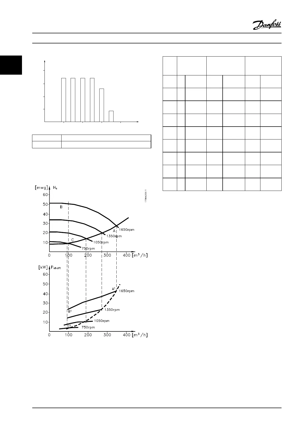
Figure 2.7 Energy Consumption at Dierent Speeds
Flow
rate
Distribution Valve regulation Adjustable
frequency drive
control
% Duration Power Consump-
tion
Power Consump-
tion
[m
3
/h]
[h] [kW
(hp)]
[kWh] [kW
(hp)]
[kWh]
350 5 438 42.5
(57)
1)
18.615 42.5
(57)
1)
18.615
300 15 1314 38.5
(52)
50.589 29.0
(39)
38.106
250 20 1752 35.0
(47)
61.320 25
(18.5)
32.412
200 20 1752 42
(31.5)
55.188 11.5
(15.5)
20.148
150 20 1752 28.0
(37.5)
49.056 6.5
(8.7)
11.388
100 20 1752 23.0
(31)
2)
40.296 3.5
(4.7)
3)
6.132
Σ
10
0
8760 – 275.064 – 26.801
Table 2.2 Result
1) Power reading at point A1
2) Power reading at point B1
3) Power reading at point C1
2.1.6
Improved Control
Using an adjustable frequency drive to control the ow or
pressure of a system improves control.
An adjustable frequency drive can vary the speed of the
fan or pump, obtaining variable control of ow and
pressure.
Furthermore, an adjustable frequency drive can quickly
adapt the speed of the fan or pump to new ow or
pressure conditions in the system.
Obtain simple control of process (ow, level, or pressure)
utilizing the built-in PI control.
2.1.7
Star/Delta Starter or Soft Starter
When large motors are started, it is necessary in many
countries to use equipment that limits the start-up current.
In more traditional systems, a star/delta starter or soft
starter is widely used. Such motor starters are not required
if an adjustable frequency drive is used.
As illustrated in Figure 2.8, an adjustable frequency drive
does not consume more than rated current.
Product Overview
VLT
®
AQUA Drive FC 202
18 Danfoss A/S © 09/2014 All rights reserved. MG20N622
22

 Loading...


