2.4.2 Control Structure Closed-loop
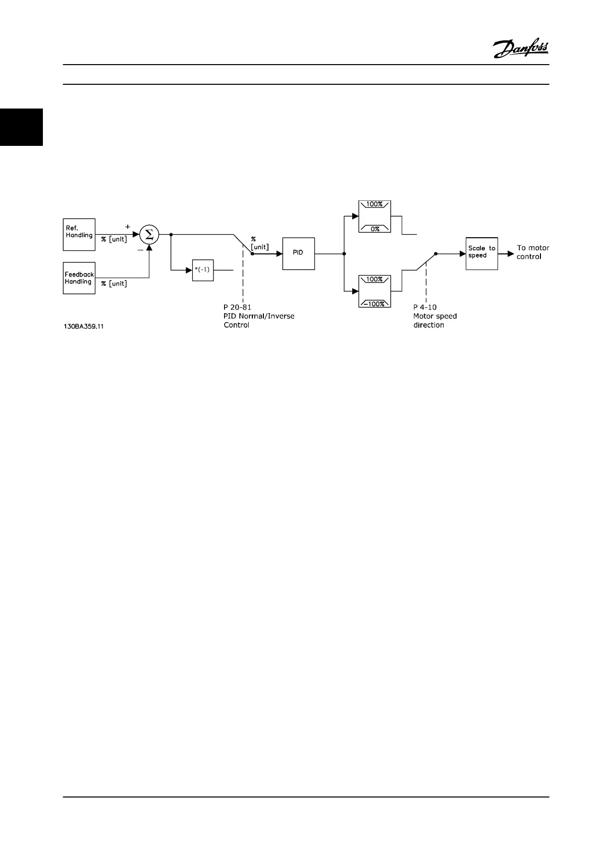
In closed-loop mode, an internal PID controller allows the
adjustable frequency drive to process system reference and
feedback signals to act as an independent control unit. The
drive can provide status and alarm messages, along with
many other programmable options, for external system
monitoring while operating independently in closed-loop.
Figure 2.12 Block Diagram of Closed-loop Controller
For example, consider a pump application in which the
speed of a pump is controlled so that the static pressure in
a pipe is constant (see Figure 2.12). The adjustable
frequency drive receives a feedback signal from a sensor in
the system. It compares this feedback to a setpoint
reference value and determines the error, if any, between
these two signals. It then adjusts the speed of the motor
to correct this error.
The desired static pressure setpoint is the reference signal
to the adjustable frequency drive. A static pressure sensor
measures the actual static pressure in the pipe and
provides this information to the adjustable frequency drive
as a feedback signal. If the feedback signal is greater than
the setpoint reference, the adjustable frequency drive
ramps downs to reduce the pressure. Similarly, if the pipe
pressure is lower than the setpoint reference, the
adjustable frequency drive ramps up to increase the pump
pressure.
While the default values for the adjustable frequency drive
in closed-loop often provide satisfactory performance,
system control can often be optimized by tuning the PID
parameters. Auto tuning is provided for this optimization.
Other programmable features include:
•
Inverse regulation - motor speed increases when
a feedback signal is high.
•
Start-up frequency - lets the system quickly reach
an operating status before the PID controller
takes over.
•
Built-in low-pass lter - reduces feedback signal
noise.
2.4.3 Local (Hand On) and Remote (Auto
On) Control
The adjustable frequency drive can be operated manually
via the LCP, or remotely via analog and digital inputs and
serial bus.
Active reference and
conguration mode
The active reference is either a local reference or a remote
reference. Remote reference is the default setting.
•
To use the local reference, congure in Hand
mode. To enable Hand mode, adapt parameter
settings in parameter group 0-4* LCP Keypad. For
more information, refer to the programming
guide.
•
To use the remote reference,
congure in Auto
mode, which is the default mode. In Auto mode,
it is possible to control the adjustable frequency
drive via the digital inputs and various serial
interfaces (RS485, USB, or an optional serial
communication bus).
•
Figure 2.13 illustrates the
conguration mode
resulting from active reference selection, either
local or remote.
•
Figure 2.14 illustrates manual conguration mode
for local reference.
Product Overview
VLT
®
AQUA Drive FC 202
22 Danfoss A/S © 09/2014 All rights reserved. MG20N622
22

 Loading...


