8.4 Cable Entry Holes
[4]
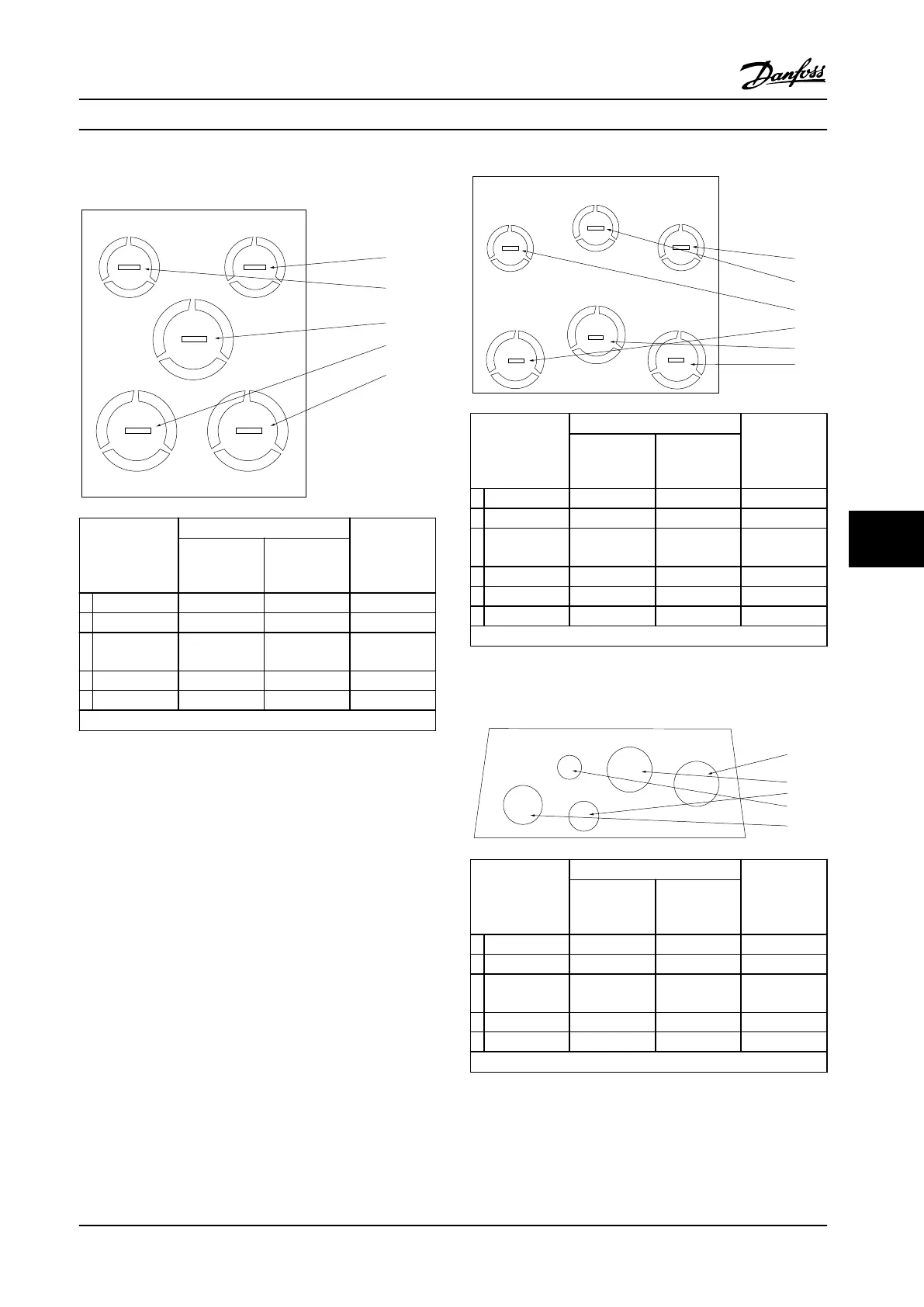
[5]
[1]
[3]
[2]
130BB656.10
Hole number
and
recommended
use
Dimensions
1)
Nearest
metric
UL [in] [mm]
1 Line power 3/4 28.4 M25
2 Motor 3/4 28.4 M25
3 Brake/load
sharing
3/4 28.4 M25
4 Control cable 1/2 22.5 M20
5 Control cable 1/2 22.5 M20
1) Tolerance ±0.2 mm
Figure 8.21 Enclosure Size A2, IP21
[4]
[5]
[6]
[1]
[3]
[2]
130BB657.10
Hole number
and
recommended
use
Dimensions
1)
Nearest
metric
UL [in] [mm]
1 Line power 3/4 28.4 M25
2 Motor 3/4 28.4 M25
3 Brake/load
sharing
3/4 28.4 M25
4 Control cable 1/2 22.5 M20
5 Control cable 1/2 22.5 M20
6 Control cable 1/2 22.5 M20
1) Tolerance ±0.2 mm
Figure 8.22 Enclosure Size A3, IP21
[5]
[3]
[2]
[4]
[1]
130BB663.10
Hole number
and
recommended
use
Dimensions
1)
Nearest
metric
UL [in] [mm]
1 Line power 3/4 28.4 M25
2 Motor 3/4 28.4 M25
3 Brake/load
sharing
3/4 28.4 M25
4 Control cable 1/2 22.5 M20
5 Removed - - -
1) Tolerance ±0.2 mm
Figure 8.23 Enclosure Size A4, IP55
Appendix - Selected Drawing... Design Guide
MG20N622 Danfoss A/S © 09/2014 All rights reserved. 201
8 8

 Loading...


