[4]
[2]
[3]
[5]
[1]
130BB665.10
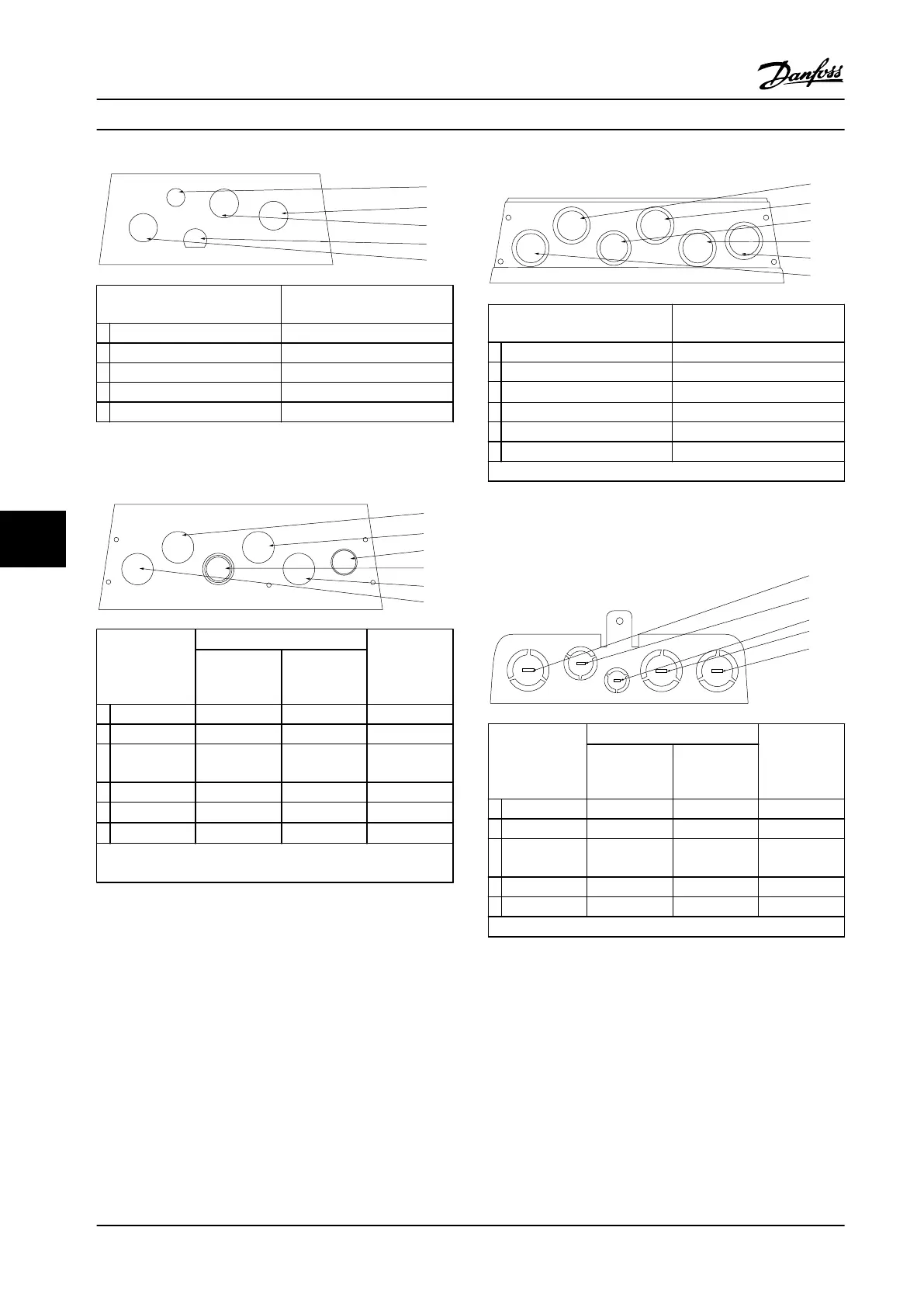
Hole number and
recommended use
Nearest metric
1 Line power M25
2 Motor M25
3 Brake/load sharing M25
4 Control cable M16
5 Control cable M20
Figure 8.24 Enclsure Size A4, IP55 Threaded Connector Holes
[3]
[4]
[5]
[6]
[2]
[1]
130BB664.10
Hole number
and
recommended
use
Dimensions
1)
Nearest
metric
UL [in] [mm]
1 Line power 3/4 28.4 M25
2 Motor 3/4 28.4 M25
3 Brake/load
sharing
3/4 28.4 M25
4 Control cable 3/4 28.4 M25
5
Control cable
2)
3/4 28.4 M25
6
Control cable
2)
3/4 28.4 M25
1) Tolerance ±0.2 mm
2) Knockout hole
Figure 8.25 Enclosure Size A5, IP55
[4]
[5]
[3]
[6]
[2]
[1]
130BB666.10
Hole number and
recommended use
Nearest metric
1 Line power M25
2 Motor M25
3 Brake/load sharing
28.4 mm (3/4 in UL)
1)
4 Control cable M25
5 Control cable M25
6 Control cable M25
1) Knockout hole
Figure 8.26 Enclosure Size A5,IP55 Threaded Connector Holes
[1]
[4]
[5]
[3]
[2]
130BB659.10
Hole number
and
recommended
use
Dimensions
1)
Nearest
metric
UL [in] [mm]
1 Line power 1 34.7 M32
2 Motor 1 34.7 M32
3 Brake/load
sharing
1 34.7 M32
4 Control cable 1 34.7 M32
5 Control cable 1/2 22.5 M20
1) Tolerance ±0.2 mm
Figure 8.27 Enclosure Size B1, IP21
Appendix - Selected Drawing...
VLT
®
AQUA Drive FC 202
202 Danfoss A/S © 09/2014 All rights reserved. MG20N622
88

 Loading...


