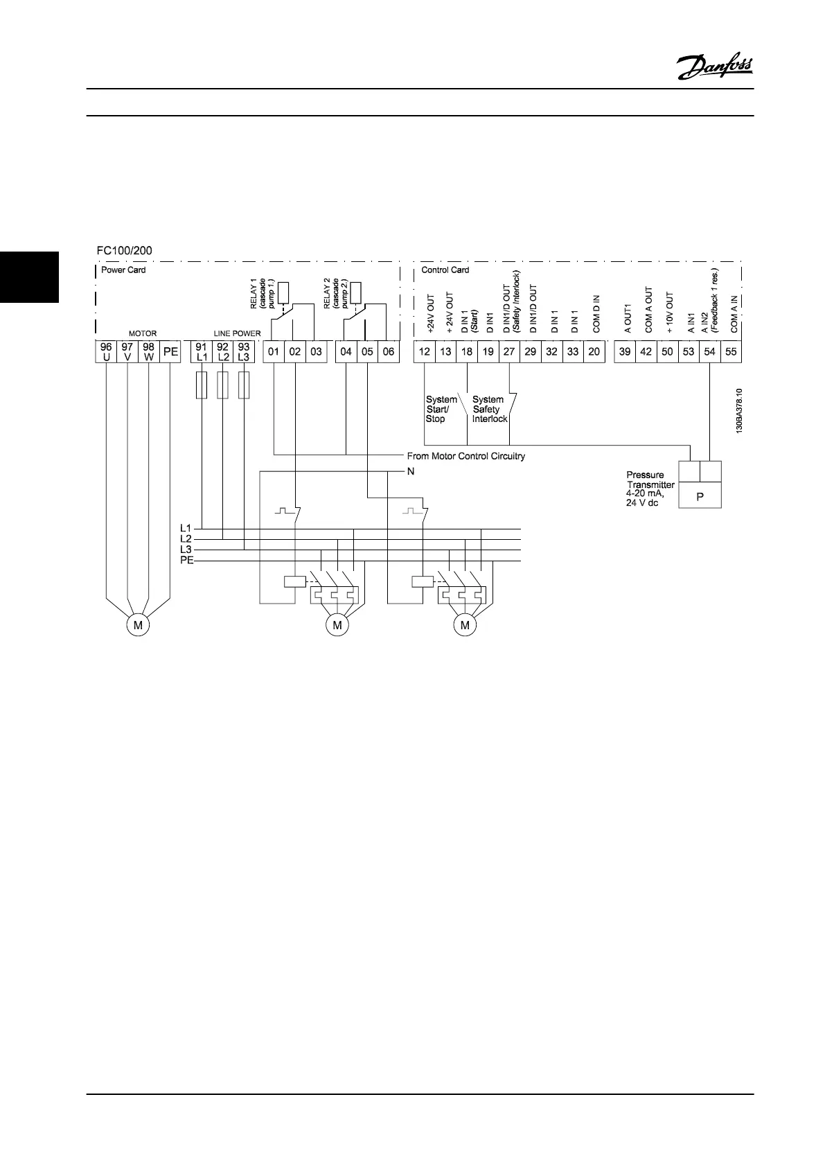
4.3.5 Cascade Controller Wiring Diagram
Figure 4.11 shows an example with the built-in BASIC cascade controller with one variable-speed pump (lead) and two xed-
speed pumps, a 4–20 mA transmitter and system safety interlock.
Figure 4.11 Cascade Controller Wiring Diagram
Application Examples
VLT
®
AQUA Drive FC 202
110 Danfoss A/S © 09/2014 All rights reserved. MG20N622
44

 Loading...


