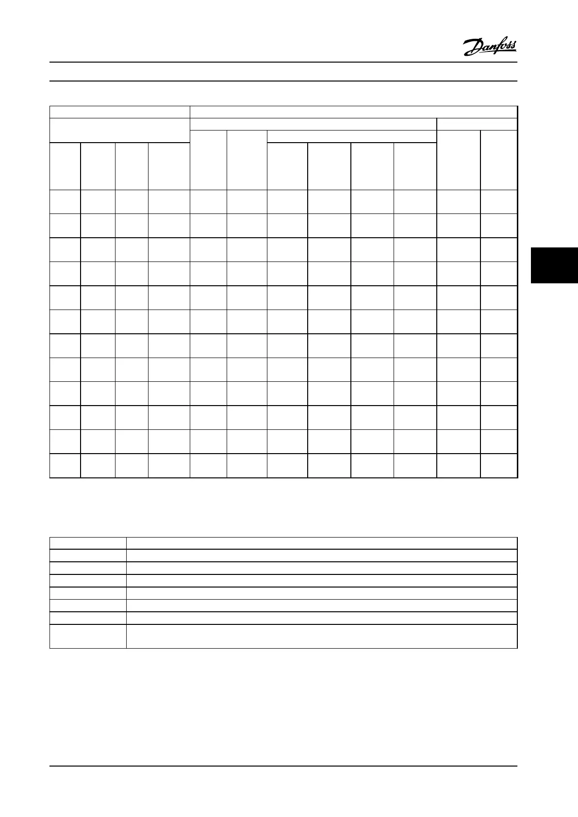
FC 202 Vertical braking 40% duty cycle
Adjustable frequency drive data
Brake resistor data Installation
R
rec
[Ω]
P
br,cont.
[kW (hp)]
Danfoss part number Cable
cross-
section
[mm
2
(AWG)]
Thermo
relay
[A]
Line
power
type
P
m
[kW
(hp)]
R
min
[Ω]
R
br,nom
[Ω]
Wire IP54
Screw
terminal
IP21
Screw
terminal
IP65
Bolt
connection
IP20
T7
315
(425)
2.3 3.7 3.2 - - - - - - -
T7
400
(550)
2.3 2.9 2.5 - - - - - - -
T7
450
(600)
2.0 2.6 2.3 - - - - - - -
T7
500
(650)
1.9 2.3 2.0 - - - - - - -
T7
560
(750)
1.5 2.1 1.6 - - - - - - -
T7
630
(850)
1.4 1.8 1.4 - - - - - - -
T7
710
(950)
1.2 1.6 2 x 2.6 - - - - - - -
T7
800
(1075)
1.1 (1.5) 1.4 2 x 2.2 - - - - - - -
T7
900
(1200)
1.0 1.3 2 x 2.0 - - - - - - -
T7
1000
(1350)
0.9 1.1 (1.5) 3 x 2.6 - - - - - - -
T7
1200
(1600)
0.8 1.0 3 x 2.4 - - - - - - -
T7
1400
(1875)
0.6 0.8 3 x 2.0 - - - - - - -
Table 6.14 T7, Vertical Braking 40% Duty Cycle, Recommended Brake Resistors
6.2.6
Alternative Brake Resistors, T2 and T4
Line power Voltage class
P
m
Rated motor size for adjustable frequency drive type
R
min
Minimum permissible brake resistor - by adjustable frequency drive
R
rec
Recommended brake resistor resistance of Danfoss brake resistors
Duty cycle P
br,cont.
x100/Pm
Part number Danfoss brake resistor order numbers
P
br,cont.
Brake resistor average rated power.
R
br,nom
The nominal (calculated) resistor value to ensure a braking energy on the motor shaft of 150/160/110% for 1
minute
Table 6.15 Abbreviations used in Table 6.16 to Table 6.17
Type code and Selection
Design Guide
MG20N622 Danfoss A/S © 09/2014 All rights reserved. 139
6 6

 Loading...


