3.4.13 Brake Resistor Cabling
EMC (twisted cables/shielding)
To meet the specied EMC performance of the adjustable
frequency drive, use shielded cables/wires. If non-shielded
wires are used, it is recommended to twist the wires to
reduce the electrical noise from the wires between the
brake resistor and the adjustable frequency drive.
For enhanced EMC performance, use a metal shield.
3.4.14 Brake Resistor and Brake IGBT
Brake resistor power monitor
In addition, the braking energy monitor function makes it
possible to read out the momentary power and the mean
power for a selected time period. The brake can also
monitor the power energizing and make sure it does not
exceed a limit selected in 2-12 Brake Power Limit (kW). In
2-13 Brake Power Monitoring, select the function to carry
out when the power transmitted to the brake resistor
exceeds the limit set in 2-12 Brake Power Limit (kW).
NOTICE!
Monitoring the braking energy does not fulll a safety
function. The brake resistor circuit is not ground leakage
protected.
The brake is protected against short-circuiting of the brake
resistor, and the brake transistor is monitored to ensure
that short-circuiting of the transistor is detected. Use a
relay or digital output to protect the brake resistor against
overloading in the event of a fault in the adjustable
frequency drive.
Overvoltage control (OVC) can be selected as an alternative
brake function in 2-17 Over-voltage Control. If the DC link
voltage increases, this function is active for all units. The
function ensures that a trip can be avoided. This is done
by increasing the output frequency to limit the voltage
from the DC link. It is a useful function, e.g., if the ramp-
down time is too short since tripping of the adjustable
frequency drive is avoided. In this situation, the ramp-
down time is extended.
3.4.15
Energy Eciency
Eciency of the adjustable frequency drive
The load on the adjustable frequency drive has little eect
on its eciency.
This also means that the adjustable frequency drive
eciency does not change when other U/f characteristics
are selected. However, the U/f characteristics do inuence
the eciency of the motor.
The eciency declines a little when the switching
frequency is set to a value above 5 kHz. The eciency is
also slightly reduced when the motor cable is longer than
30 m (100 ft).
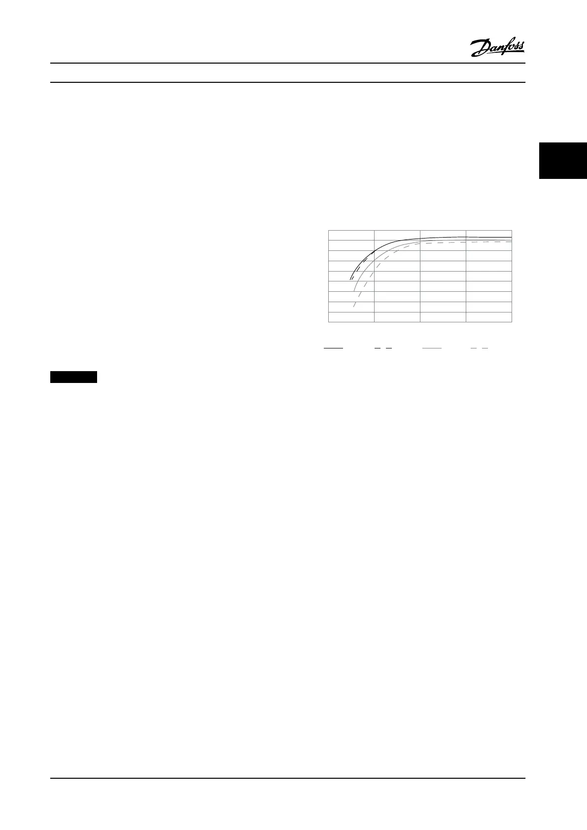
Eciency calculation
Calculate the eciency of the adjustable frequency drive at
dierent loads based on Figure 3.19. Multiply the factor in
this graph with the specic eciency factor listed in
chapter 7.1 Electrical Data.
1.0
0.99
0.98
0.97
0.96
0.95
0.93
0.92
0% 50% 100% 200%
0.94
Relative Eciency
130BB252.11
1.01
150%
% Speed
100% load 75% load 50% load 25% load
Figure 3.19 Typical Eciency Curves
Example: Assume a 55 kW (75 hp), 380–480 V AC
adjustable frequency drive with 25% load at 50% speed.
The graph is showing 0.97 rated eciency for a 55 kW (75
hp) adjustable frequency drive is 0.98. The actual eciency
is then: 0.97 x 0.98=0.95.
Motor eciency
The eciency of a motor connected to the adjustable
frequency drive depends on magnetizing level. The
eciency of the motor depends on the type of motor.
•
In the range of 75–100% of the rated torque, the
eciency of the motor is practically constant,
both when it is controlled by the adjustable
frequency drive, and when it runs directly on line
power.
•
The inuence from the U/f characteristic on small
motors is marginal. However, in motors from 11
kW (15 hp) and up, the eciency advantage is
signicant.
•
The switching frequency does not aect the
eciency of small motors. Motors from 11 kW (15
hp) and up have their eciency improved 1–2%.
This is because the sine-shape of the motor
current is almost perfect at high switching
frequency.
System eciency
To calculate the system eciency, multiply the eciency of
the adjustable frequency drive by the eciency of the
motor.
System Integration
Design Guide
MG20N622 Danfoss A/S © 09/2014 All rights reserved. 63
3 3

 Loading...


