8 Appendix - Selected Drawings
8.1 AC Line Input Connection Drawings (3-
phases)
This collection of drawings is intended to aid planning for
access, in the design phase.
Refer to the instruction manual for installation procedures
including:
•
Safety requirements.
•
Step-by-step installation procedures.
•
Alternative congurations.
•
Additional drawings.
AC line input connection for enclosures A1, A2 and A3:
+DC
BR-
BR+
U
V
W
MAINS
L1 L2 L3
91 92 93
RELAY 1 RELAY 2
99
- LC -
130BA264.10
Figure 8.1 Support Bracket
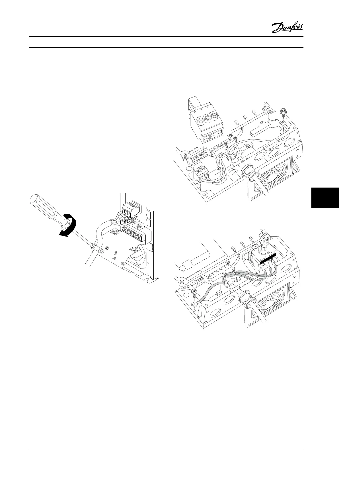
AC line input connection for enclosures A4/A5
L 1
L 2
L 3
91
92
93
130BT336.10
Figure 8.2 Line Power and Grounding without Disconnector
Figure 8.3 Line Power and Grounding with Disconnector (for
S2 variants in enclosure size B2, the extra terminal block must
be used for AC line input connection.
When disconnector is used (enclosures A4/A5), mount the
PE on the left side of the adjustable frequency drive.
Appendix - Selected Drawing... Design Guide
MG20N622 Danfoss A/S © 09/2014 All rights reserved. 195
8 8

 Loading...


