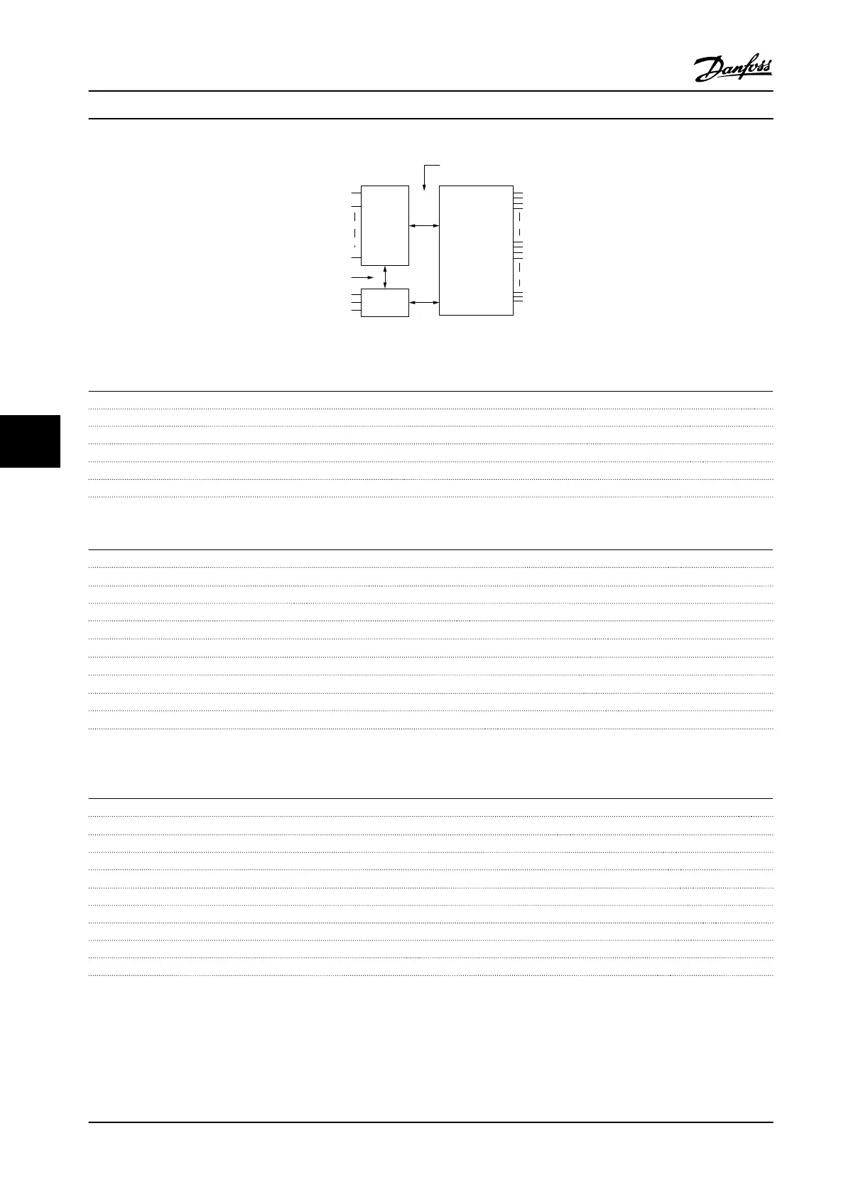
Mains
Functional
isolation
PELV isolation
Motor
DC-Bus
High
voltage
Control
+24V
RS485
18
37
130BA117.10
Figure 7.1 PELV Isolation of Analog Inputs
Analog output
Number of programmable analog outputs 1
Terminal number 42
Current range at analog output 0/4–20 mA
Maximum resistor load to common at analog output 500 Ω
Accuracy on analog output maximum error 0.8% of full scale
Resolution on analog output 8 bit
The analog output is galvanically isolated from the supply voltage (PELV) and other high-voltage terminals.
Digital inputs
Programmable digital inputs 4 (6)
Terminal number 18, 19, 27
1)
, 29
1)
, 32, 33,
Logic PNP or NPN
Voltage level 0–24 V DC
Voltage level, logic 0 PNP <5 V DC
Voltage level, logic 1 PNP >10 V DC
Voltage level, logic 0 NPN >19 V DC
Voltage level, logic '1' NPN <14 V DC
Maximum voltage on input 28 V DC
Input resistance, R
i
approx. 4 kΩ
All digital inputs are galvanically isolated from the supply voltage (PELV) and other high-voltage terminals.
1) Terminals 27 and 29 can also be programmed as output.
Digital output
Programmable digital/pulse outputs 2
Terminal number 27, 29
1)
Voltage level at digital/frequency output 0–24 V
Maximum output current (sink or source) 40 mA
Maximum load at frequency output 1 kΩ
Maximum capacitive load at frequency output 10 nF
Minimum output frequency at frequency output 0 Hz
Maximum output frequency at frequency output 32 kHz
Accuracy of frequency output maximum error 0.1% of full scale
Resolution of frequency outputs 12 bit
1) Terminal 27 and 29 can also be programmed as input.
The digital output is galvanically isolated from the supply voltage (PELV) and other high-voltage terminals.
Specications
VLT
®
AQUA Drive FC 202
168 Danfoss A/S © 09/2014 All rights reserved. MG20N622
77

 Loading...


