V0913, 10.45
For the lower side of the machine the height is defined from the table surface to the floor level.
After giving in the base parameters for the specific machine part, the drawing editor appears.
Similar to drawing of tools, also the details of the machine parts can be drawn. Either by
tapping and sketching or by giving in the length of sides and pointing the direction of the next
side.
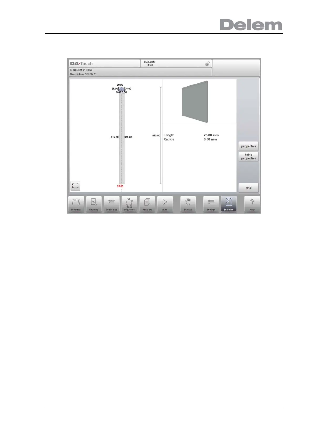
Mounting point
Within the drawing one also finds the mounting point of the table. This point, indicated with the
triangle arrow, shows at what point the die or adapter will be connected and placed on the
table.
When an I-axis is present in the system also the I-axis division line will be shown. This line, by
default positioned at the top level of the table, can be pulled down on levels in the drawing.
This level can be the division between the tool holder and the actual table. The division line
defines the stationary and dynamic part of the table. All above the dashed line, e.g. the tool
holder, will move with the I-axes.
Specifically with the mounting point of the table also the I-axis position is defined. By default
this I-axis value is 0, meaning when the I-axis position is set to 0 the mount point will be
positioned at the centre of the machine (X=0). Upon choise one can change this value giving
an offset to the I-axis range.
Mounting points can also be found in dies and adapters. When this function is not enabled,
the indicator is not shown.