V0913, 4.1
4. Tool configuration
4.1. Introduction
4.2. Standard procedure
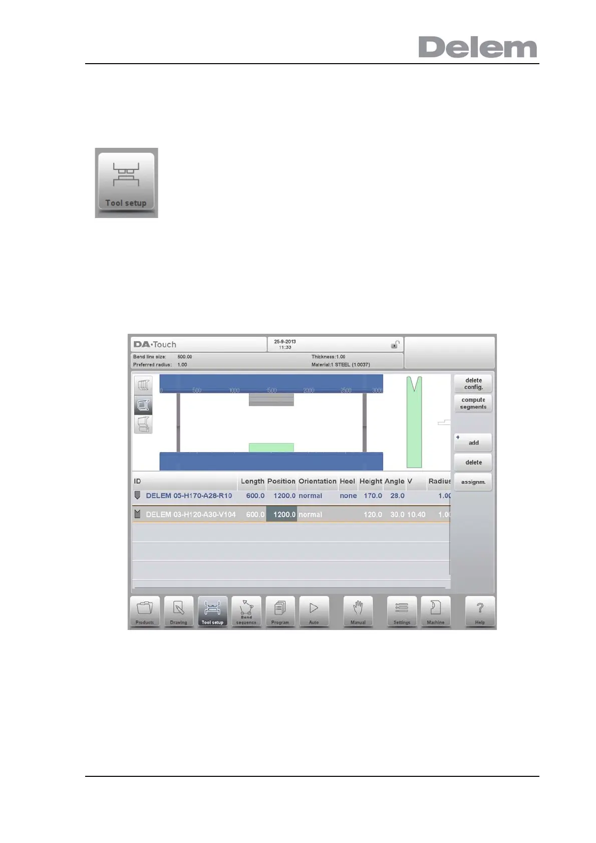
When the function Tool Setup has been activated, the screen shows a front view of the
machine set-up in the upper half of the screen. In the lower half of the screen, the tool data is
displayed. In this screen, the placement of tools in the machine can be programmed.
In the front view, the following machine elements are shown, from top to bottom:
• Machine upper side (pressing beam)
• Adapter for punch (if an adapter is programmed)
•Punch
•Die
• Machine lower side (table).
The machine parts have already been pre-selected in the Machine mode. Normally these
parts will not change. Whether an adapter can be programmed depends on the parameter
Enable Adapters in the same Machine mode.
To edit or modify a tool setup for the product, select the product
from the library and use Tool Setup