V0913, 2.15
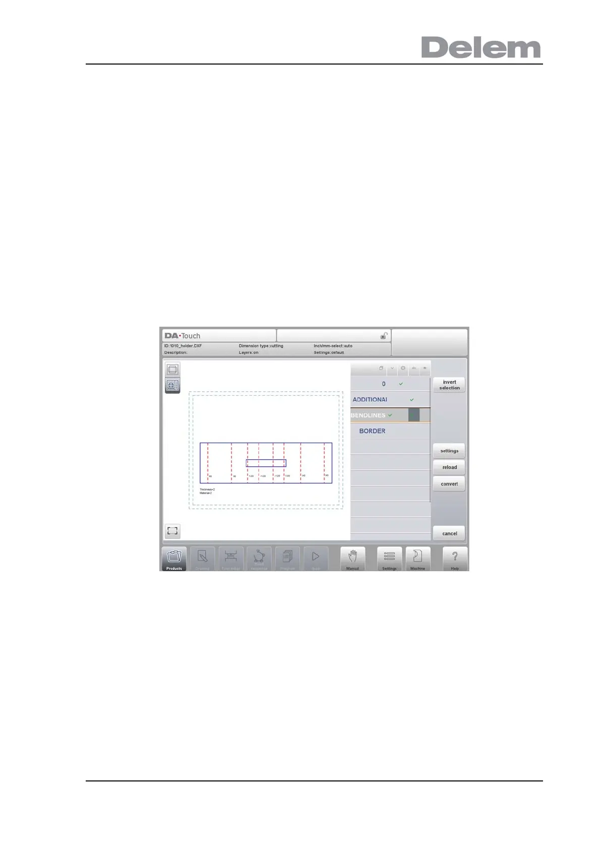
Layer selection switched on
With layer selection on, the available layers in the DXF are shown in the list.
In the header the symbols of angle, contour, text and visualisation are shown and indicate the
layer assignment. Each layer can be assigned to the specific property column by checking a
checkbox. The layer can be assigned as bendlines or contour lines. The texts can be
assigned as special information. This as configured in Settings::Labels.
The visualisation switches a complete layer off or on. This does not exclude it from the later
conversion.
If no checkmarkers are set a layer will be skipped during conversion.
When tapping the layer name, the lines from that layer will be indicated.
The drawing will be visualised in dashed lines before any line is assigned.
When lines have been assigned following colors will indicate the assignment:
• Blue: Contour line, this line is a part of the outer contour of the product.
• Red: Bend line, this line is a bending.
• Black: Assigned texts will be shown in black.
For bendlines, lines as well as texts can be checked. The text near the line indicates its angle
value or radius or if it is a hemming. When assigning text to bendlines, the import will use this.
For countour lines text information is not applicable.
The product properties, eg. sheet thickness and material, can be imported as text, based on
the labels set in the DXF conversion settings.