V0913, 2.13
2.2.1. Product drawing dimensions
The drawing file can be organised in two ways:
• projection dimensions;
• cutting dimensions.
These ways are described in the following subparagraphs.
During operation in the DXF converter, it is possible to switch between cutting dimensions and
projection dimensions. This can be done in the DXF conversion settings.
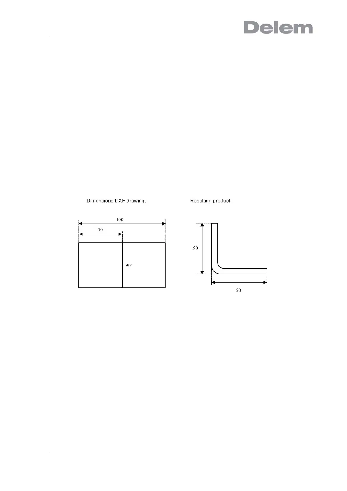
Projection dimensions
In this situation all product sides and bend lines have the length of the resulting product. The
drawing does not represent the real size of the sheet that must be bent, but is merely a
representation of how the sheet is to be organised into bends and surfaces. When such a
drawing is loaded and converted, the converter will construct a product drawing with exactly
the same sizes as are present in the original drawing. Later on additional information is added
about material, sheet thickness and product dimensions. It is left to the control to create a
CNC program with proper axes positions that will result in a product as intended.
In this example, the length in the original DXF drawing may simply be 100, separated by a
bendline. The resulting product will consist of two sides, each with a length of 50.
The dimensions are defined as outside dimensions.
Cutting dimensions
In this case the DXF drawing represents the exact sheet, as it is cut and will be used to bend
a product of. When the DXF converter is set to convert cutting dimensions, based on material
and thickness of the sheet, bend allowance information is required during the conversion
process. If this information is not present the converter will ask for it.
The converter will use these dimensions and a bend-allowance table to construct a 3D
product drawing with projection dimensions. When the product is used in the control, the
same bend allowance table should be used to create a CNC program that can process a
sheet as shown in the original DXF drawing.