V0913, 10.34
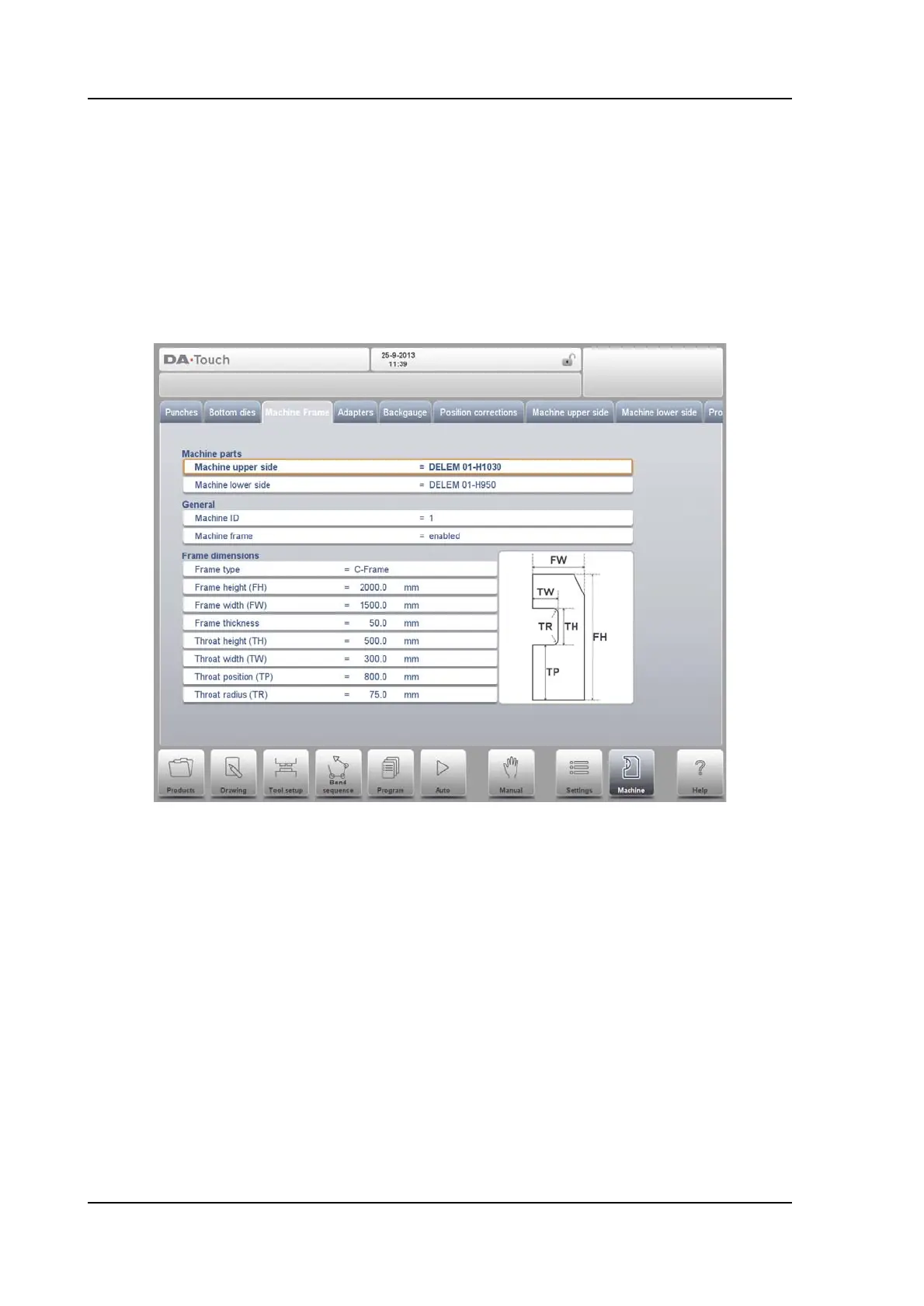
10.4. Machine frame
On this tab the active machine geometries from upper and lower beam and the side frames,
can be selected and set. Also the machine identification can be programmed here.
Next to the Machine Upper Side and Machine Lower Side which are chosen from those
available, the Side frame dimensions can be programmed in this page.
The machine shape is shown in the simulation screen during graphical programming and
used for the collision detection for work piece against machine.
Watch the on-screen picture for the parameter meaning.
At the top of the screen the possible machine parts can be selected. The selected machine
parts are used when a new tool configuration is programmed.
Machine upper side
Select the relevant machine upper side.
To search for the correct machine parts, press the function Filter View in the keyboard.
Machine lower side
Select the relevant machine table.
To search for the correct machine parts, press the function Filter View in the keyboard.
Machine ID
When there are several bending machines in a factory, it can be useful to give the
control on each machine a unique machine ID.
This ID will be checked when a program is read from a back-up medium. When the
machine ID does not match you must confirm to read it anyway or not. If you do not
confirm the question the action will be aborted.