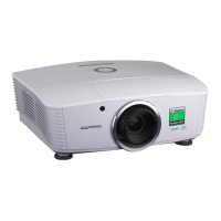
Signal Inputs and Outputs
Inputs 1-8, on the rear of the projector, are limited input frame rates up to 60Hz, but
provide access to the full geometric adjustment capabilities, including Blend and
Warp.
The side inputs 9, 10 and 11 on 3D projectors provide a very direct path to
the DMD™ display, with minimal latency and high frame rate capability. Their
geometrical adjustment capabilities are limited in comparison with inputs 1-8.
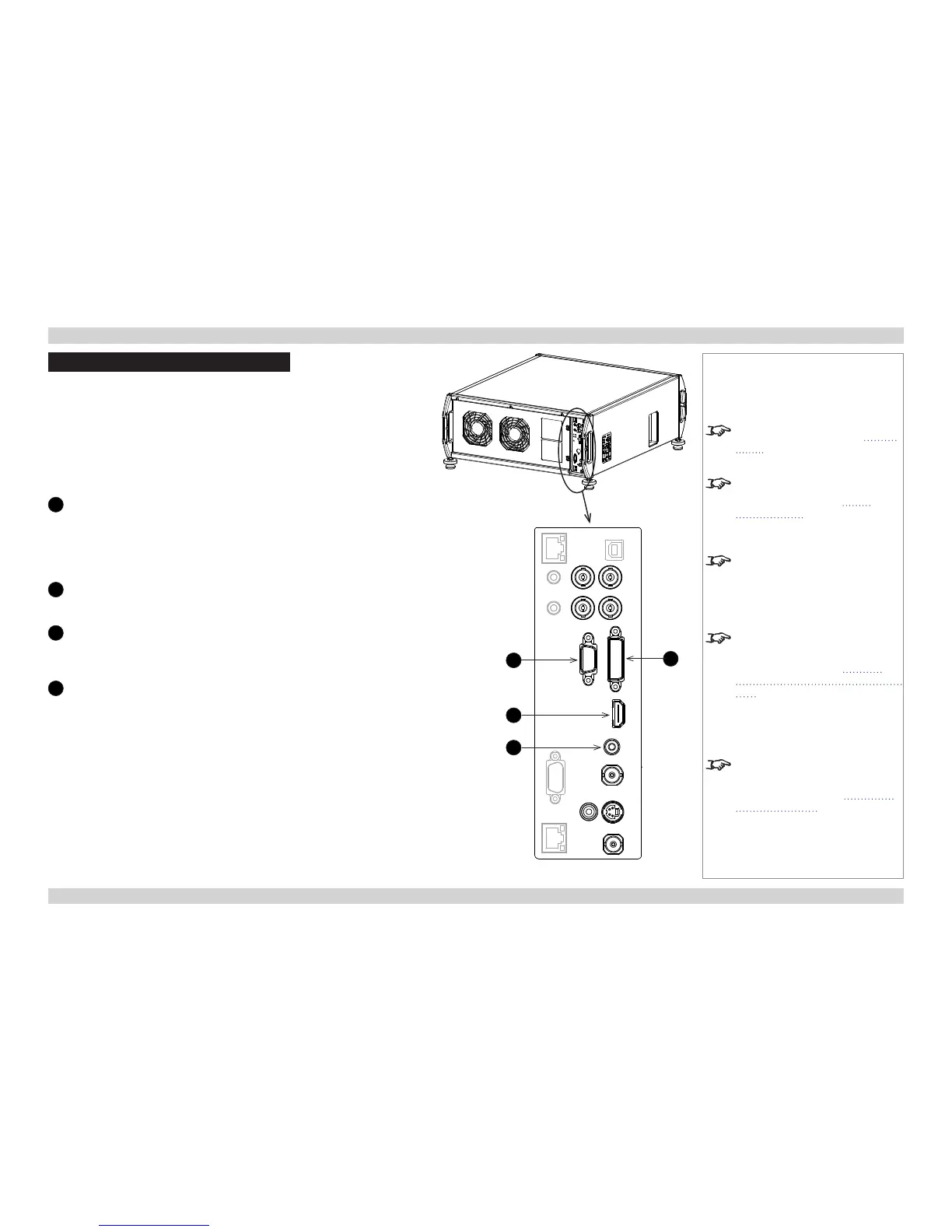
Rear connection panel
1
VGA (input 1)
Receives analog signal from a computer. When using this input, it is best
to use a fully wired VGA cable (with a blue connector shell) to connect
the source to the projector. This will allow the source to determine the
projector’s capabilities via DDC and show an optimized image.
Use Auto Setup in the Image/VGA Setup menu.
2
HDMI (input 2)
Receives digital signal from HDMI-compliant devices. The audio from the
HDMI 1 source is available on the SPDIF output.
3
SPDIF
This is a digital output.
Compatible audio sample packets on the HDMI input stream are decoded
by the projector and output on the SPDIF connector.
4
DVI (input 3)
Analog or Digital DVI-I
This input has a DVI-I connector, which can receive either analog (DVI-A)
or digital (DVI-D) signal from a compatible source.
Set DVI-I Port in the Setup/InputConguration menu to choose
between Analog and Digital.
Sources up to:
• 1920x1080 resolution for 1080p models
• 1920x1200 resolution for WUXGA models
24-60Hz; up to 12 bits per color. Supports HDCP.
(the list continues overleaf)
Notes
For more VGA settings, see Image
menu in the Operating Guide.
For further information on setting
up the DVI 1 input, see Input
Configuration in the Operating
Guide.
WUXGA (1920x1200) is only
available at 50 and 60Hz on Input 3.
For WUXGA 3D, we recommend the
use of Input 9.
For more information about
the difference between the two
connection panels, see Special
considerations when using inputs
9-11 further in this section.
For a complete listing of pin
congurations for all signal and
control connectors, see Appendix
E: Wiring Details in the Reference
Guide.
Rear Connection Panel
2
4
3
1
 Loading...