Subnetwork Installation Guidelines
136 ECLYPSE User Guide
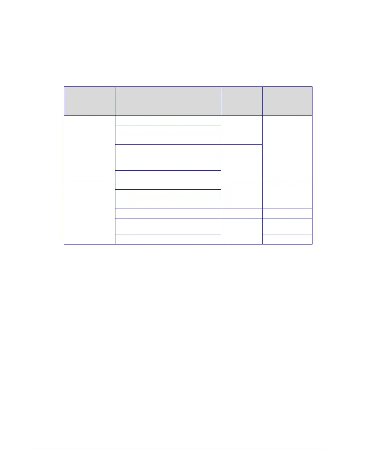
Subnetwork Module Compatibility and Supported Quantity
Charts
Not all subnetwork modules work with all controller models: The subnetwork module
compatibility for an individual controller is shown in the table below along with the maximum
supported quantity of room devices and extension modules. The Subnet ID address of all
subnet devices must be set to be within the shown addressing range.
Subnetwork Data Bus Device
Permitted
Subnet ID
Addressing
Range
Allure EC-Smart-Vue series
Allure EC-Smart-Comfort series
Allure EC-Smart-Air series
ECx-Light-4 / ECx-Light-4D /
ECx-Light-4DALI
ECx-Blind-4 / ECx-Blind-4LV
Allure EC-Smart-Vue series
Allure EC-Smart-Comfort series
Allure EC-Smart-Air series
ECx-Light-4 / ECx-Light-4D /
ECx-Light-4DALI
ECx-Blind-4 / ECx-Blind-4LV
Table 12-2: Subnetwork Module Compatibility and Maximum Supported Quantity
Chart
1. See the room device calculator spreadsheet available for download from our website to
know the permitted quantities for these controller models: VAV-Smart Room Control
Device Calculator.xlsm
2. Light and blind/shade expansion modules share the same Subnet ID addressing range.
For example, you cannot set both an ECx-Light-4 and an ECx-Blind-4 to have a Subnet
ID as 1.
3. A controller can support a maximum of two (2) Allure series sensor models equipped
with a CO
2
sensor. Any remaining connected Allure series sensor models must be
without a CO
2
sensor.
4. These models support a recommended maximum of 4 sensors (Allure series sensors
and EC-Multi-Sensor series) combined in total. Each Allure series sensor model
equipped with a CO
2
sensor counts as 2 sensors (for example, you cannot connect any
other sensors if you connect two Allure series sensor models equipped with a CO
2
sensor or you can connect up to two other non-CO
2
sensors if you connect one Allure
series sensor models equipped with a CO
2
sensor). When a longer system response
time is acceptable, up to 4 Allure series sensors (no more than 2 of which are equipped
with a CO
2
sensor) and up to 4 EC-Multi-Sensor series can be connected in total.
Subnetwork Module Connection
The following sections will provide further information needed to connect and configure the
subnetwork devices such as cable type, cable length, wiring, data bus termination, device
addressing, and more.