Modbus RTU Communication Data Bus Fundamentals
156 ECLYPSE User Guide
Maximum Number of Modbus RTU Devices on a
Data Bus Segment and Baud Rate
The number of Modbus devices supported by an ECY Series Controller is software limited
according to the controller model purchased. See the controller’s datasheet for more
information. For ECY Series Controller models that are not software limited, the controller
can support a combined maximum of 32 Modbus RTU and Modbus TCP devices.
Data Bus Segment Addressing Range for Modbus RTU
Devices
The Modbus RTU device address range is 1 to 254. Address 0 is used to broadcast
messages to all slave devices and write only. When address 0 is used to broadcast a
message, there is no confirmation that the message was properly received by any slave
device.
However, it is recommended that any given data bus segment have no more than 50
devices, when a baud rate of 19 200 or higher is used for the Modbus RTU Data Bus. A
repeater counts as a device on each data bus segment to which it is connected.
Baud Rate
Most devices will have a range of baud rate settings and possibly an AUTO setting that
detects the baud rate of other devices transmitting on the data bus and adjusts the baud rate
of the device accordingly. Typical baud rates are 9600, 19 200, 38 400, and 76 800. The
baud rate setting determines the rate at which data is sent on the Modbus RTU data bus.
All devices on the data bus must be set to the same baud rate. Therefore, the chosen baud
rate must be supported by all devices connected to the data bus.
The recommended baud rate is 38 400.
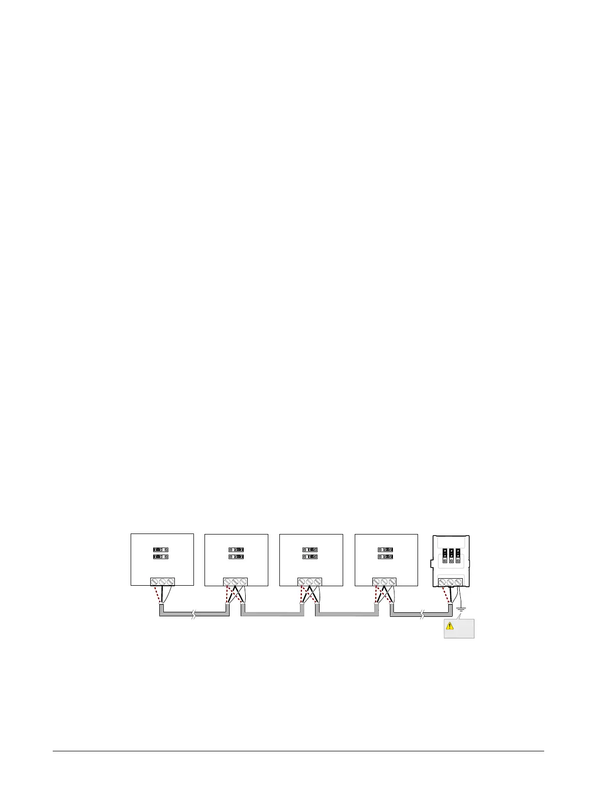
We recommend that you:
Set the baud rate of two controllers on a Modbus RTU Data Bus Segment to the same
baud rate to provide failover protection.
For example, set the baud rate of the ECY Series Controller (if equipped) and one other
controller to 38 400 baud. If the ECY Series Controller becomes unavailable and there is
a power cycle, the controller will set the baud rate for the Modbus RTU Data Bus.
Set all other devices to automatically detect the baud rate, if this option is available.
ECY Series
NET-
NET +
S
Typical Modbus RTU
Device
Typical Modbus RTU
Device
Typical Modbus RTU
Device
Typical Modbus RTU
Device
EOL ON
EOL OFF
EOL OFF
EOL OFF
Data Bus: Shielded Twisted Pair Cable
Electrical
System
Ground
Baud: Auto (Factory Default) Baud: Auto (Factory Default) Baud: Auto (Factory Default) Baud: 38 400
Baud: 38 400
EOL
ON
NET-
NET +
S
NET-
NET +
S
NET-
NET +
S
NET-
NET +
S
Figure 14-1: Setting the Baud rate on two Controllers on a Modbus RTU Data Bus
Segment for Failover Protection
Set the Modbus network communication parameters with EC-gfxProgram in the Resources
Configuration window, Modbus Device block.