Above Ground Model 200iX/250iX Motorcycle Dynamometer Installation Guide
3-14
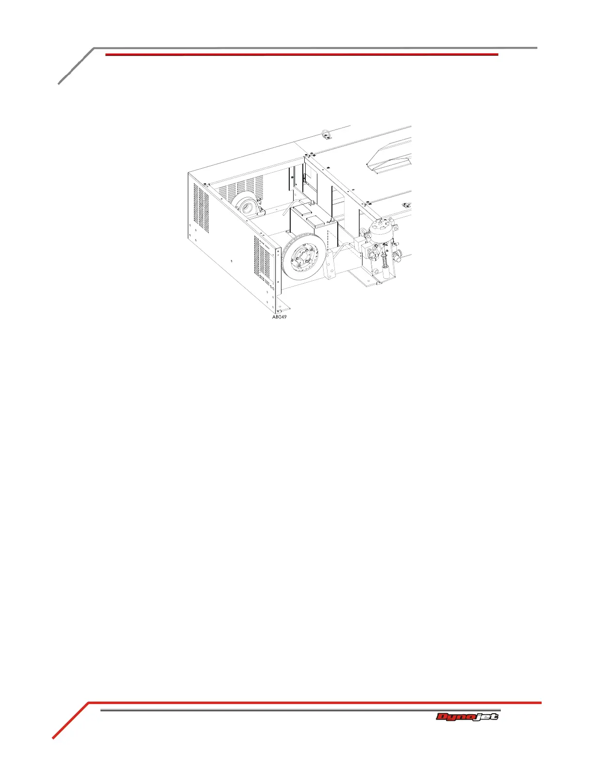
10 Lift the air brake assembly up and away from the dyno.
Figure 3-17: Remove the Brake Assembly
11 Remove the brake pad retaining springs and slide the pads out.
Note: You will need to use pliers to remove the spring securing the outside pad
(closest to the castle nut).
12 Install the new brake pads and secure the pads with new springs.
13 Place the air brake assembly back on the brake bracket. Refer to Figure 3-17.
14 Replace the top and bottom clevis pins and secure with the hairpin cotters
removed earlier. Refer to Figure 3-14, Figure 3-15, and Figure 3-16.
15 Using two bolts and two washers, secure the brake caliper stop to the brake
bracket. Refer to Figure 3-13.
16 Secure the spring using the bolt, washer, and nut you removed earlier. Refer to
Figure 3-12.
17 Tighten the castle nut and replace the hair pin cotter. Refer to Figure 3-11.
18 Adjust the brake pad clearance. Refer to“Adjusting the Brake Pad Clearance” on
page 3-15 for complete instructions.
19 Replace the top and right side covers.
20 Connect your shop air.