APPENDIX D
Ramp Installation—iX Upgrade
Above Ground Model 200iX/250iX Motorcycle Dynamometer Installation Guide
D-12
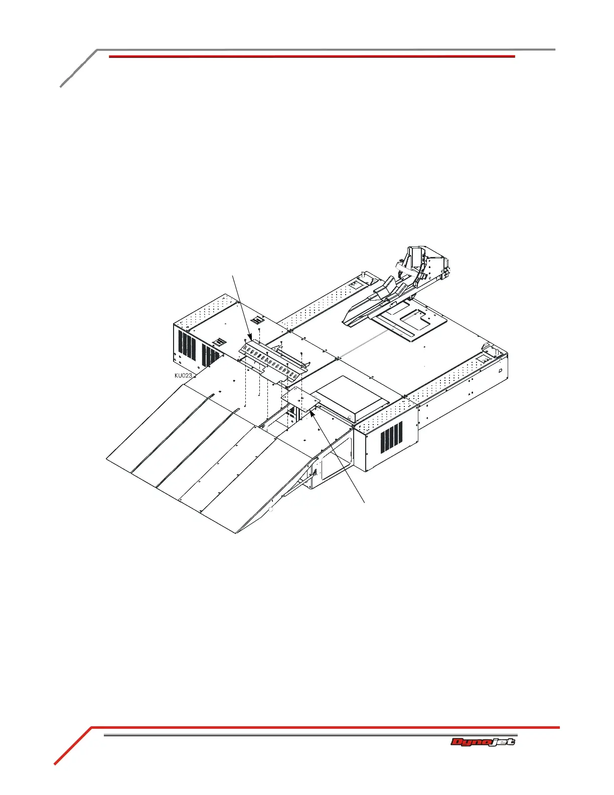
7 Remove the four existing 1/4-20 x 5/8-inch screws from the dyno ramp as shown
in Figure D-12.
8 Remove the two existing 1/4-20 x 5/8-inch screws from the iX ramp as shown in
Figure D-12.
9 Secure the ramp tie-down to the dyno ramp using the four screws removed earlier.
10 Secure the ramp tie-down to the iX ramp using the two screws removed earlier.
11 Place the ramp cover as shown in Figure D-12.
Note: The ramp cover provides easy access to the air pump filter assembly.
12 Route the air fuel hoses through the large holes in the ramp cover.
Figure D-12: Securing the Ramp Tie-Down