15 / 97
Introduction Manual ENC66
eckelmann.de
The following files are reserved for the firmware of the controllers:
Tab elle 6:
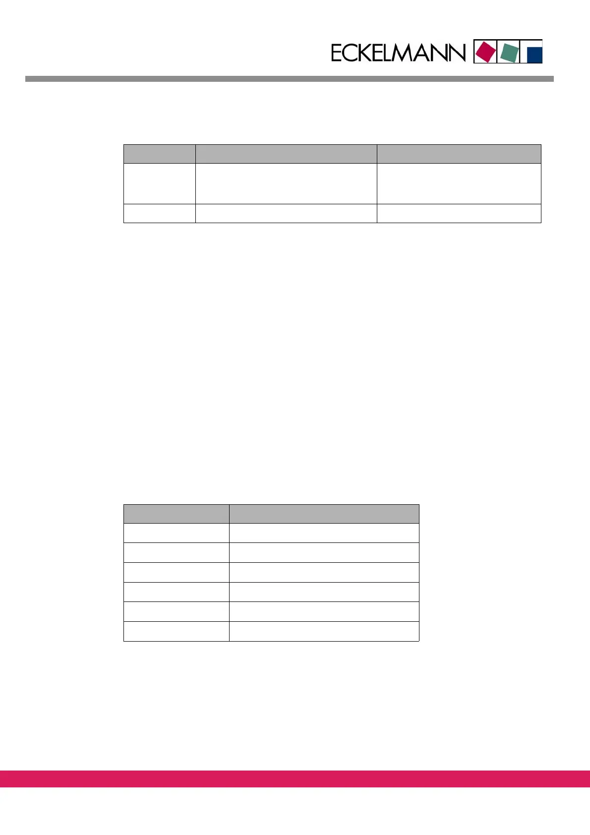
Table 6: Firmware files
File Description Installation via bootloader
BOOT66.BIN Bootloader for installing the NC
f
irmware. It has netboot functionality to
reload the firmware via the StdHMI
ENC66.RSC NC firmware for the ENC66 x
Other filenames with the extension „.rsc“ and the name „boot*.bin“ must not be used.
1.4 Status information of the ExC66
Besides 3 status LED, a 7-segment indicator is available on the assembly which indicates the
current operating state and probable faults of the assembly, depending on the operating
state.
In current operation, the 7-segment indicator is u
sed as status information. In case of a soft-
ware error, the occurring error is indicated in
the form of a defined string of characters.
The green LED indicates the watchdog function and is lit if no malfunction occurs. The two
o
ther LED are used to indicate the CAN1 state. In case of the 7-segment indication a distinc-
tion is made between booting and operation.
1.4.1 Status information during booting
At the beginning of booting, a memory test is made and the firmware is loaded. In this
phase, the following indications are made.
Tab elle 7:
Table 7: 7-segment indicator, Status information during booting
7-segment indicator Meaning
0 Hardware initialization
1 RAM test
2 Initialization terminated
3 Loading of firmware from FROM to RAM
4 Firmware loaded
5 Firmware started