73 / 97
Introduction Manual ENC66
eckelmann.de
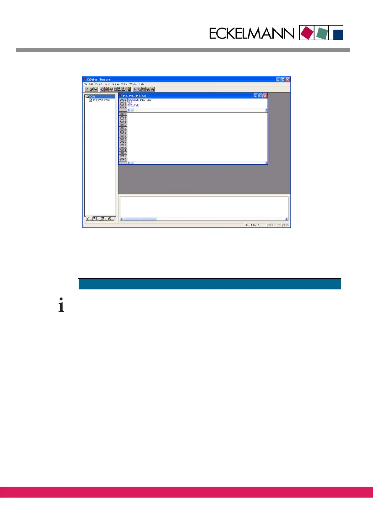
Abbildung 47:
Figure 47: The empty program block
9.4.2 General instructions for the address mapping of IO modules
9.4.2.1 Limitations of FBM modules
CAN-Modules can only be located from byte address 128 or word address 64 onwards.
9.4.2.2 General instructions for the PLC configuration with LBM modules
All used LBM modules must have entries in the
CoDeSys PLC configuration. The following
modules, that are automatically handled by the controller, are excluded:
• Analog axes, that are realized with LBM ARI01
modules for CNC or motion applica-
tions.
• Communication interfaces that are realized with LBM
SER02 modules.
Modules, that have no corresponding entry in the PLC configuration, are ignored by the
co
ntroller. The LIFE-LED stays unlit. The process image isn‘t updated and the outputs stay
switched off.
Example for a PLC configuration with LBM modules: