71 / 97
Introduction Manual ENC66
eckelmann.de
Abbildung 44:
EExC66
WDOG
LED2
LED1
USB Ethernet RS232 CAN2
CAN3CAN4SD-Card
1
2
4
3
CAN
Term
SD
WD 2 WD 1 C_GD C_H C_ L PE
E-Control ExC66 with power supply and LBM IO modules
5V
24V
5A
24V 24V 0V 0V
ELBM
PWR04
24V 24V 0V 0V
ELBM
DIM 16
I 5
I 4
I 3
I 2
I 1
24V
LIFE
I 6
I 7
I 8
0V
I 13
I 12
I 11
I 10
I 9
24V
I 14
I 15
I 16
0V
24 V 0 V
CAN1
Watchdog
CAN3
CAN4
CAN2
Ethernet
24V 24V 0V 0V
ELBM
DOM 16
O 5
O 4
O 3
O 2
O 1
24V
LIFE
O 6
O 7
O 8
0V
O 13
O 12
O 11
O 10
O 9
24V
O 14
O 15
O 16
0V
Tool down (I_ToolDown)
Tool up (I_ToolUp)
Emergency stop (I_NoEStop)
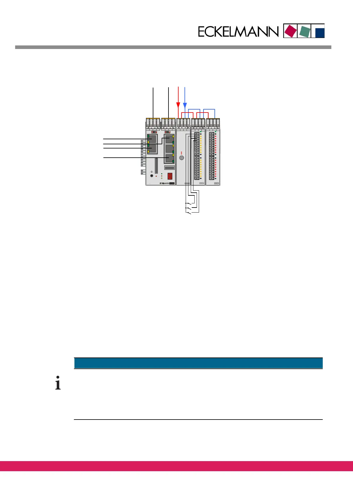
Figure 44: Controller setup for the example
• The 24V voltage is connected with the modules LBM PWR04, LBM DOM16 and LBM
DIM16
• A signal „Tool down“ (I_ToolDown) of the tool is connected with the input I1 of the
LBM DIM
16
• A signal „Tool up“ (I_ToolUp) of the tool is conn
ected with the input I2 of the LBM
DIM16
• A signal „Emergency stop circuit“ (I_NoEStop) of the drives is connected with the
input
I3 of the LBM DIM16
• A switch „Lower Tool” (O_ToolDown) is connected with the output O1 of the LBM
DOM16
9.4 Configuration of a controller in ETOOLS PLC/2
The following chapter describes the general procedure of the configuration of the control-
ler as prerequisite for the generation of a prog
ram under ETOOLS PLC2 (For further details
please check /1/).
This chapter can be skipped if the sample program CNC_Test is used, because the described
settings of an ENC66 are already available there.