22 / 97
2 Connection and installation
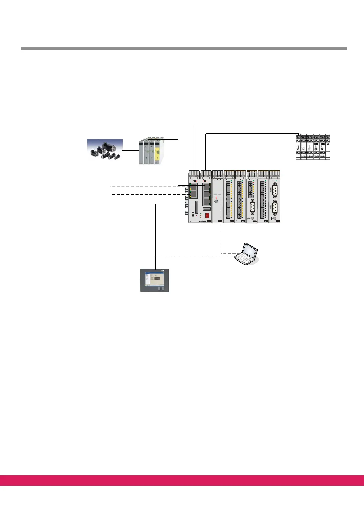
2.1 Example of a structure
Abbildung 3:
E-Control ExC66 with power supply and
LBM IO modules
CAN1
Ethernet
FIPC
FBM modules
CAN2
CAN3
CAN4
Other servo
controllers
E-DARC
RS-232
Watchdog
Service
EExC66
WDOG
LED 2
LED 1
USB Ethernet RS232 CAN2
CAN3CAN4SD-Card
1
2
4
3
CAN
Term
SD
WD 2 WD 1 C_ GD C_H C_L PE
5V
24V
5A
24V 24V 0V 0V
ELBM
PWR 04
24V 24V 0V 0V
ELBM
DIM 16
I 5
I 4
I 3
I 2
I 1
24V
LIFE
I 6
I 7
I 8
0V
I 13
I 12
I 11
I 10
I 9
24V
I 14
I 15
I 16
0V
24V 24V 0V 0V
ELBM
DIM16
I 5
I 4
I 3
I 2
I 1
24V
LIFE
I 6
I 7
I 8
0V
I 13
I 12
I 11
I 10
I 9
24V
I 14
I 15
I 16
0V
E
n
c
o
d
e
r
D
i
g
i
t
a
l
I
N
/
A
n
a
l
o
g
O
U
T
24V 24V 0V 0V
ELBM
ARI01
I4
I3
I2
I1
REL
REL
LIFE
DCOM
AO1
ACOM
24V 24V 0V 0V
ELBM
AIO 22
AI2+
0V
24V
SHLD
AI1-
AI1 +
LIFE
AI2-
SHLD
24V
0V
OCOM
AO1
SHLD
10V
10V
PE
SHLD
AO2
OCOM
SHLD
24V 24V 0V 0V
ELBM
DOM 1 6
LIFE
E-Motors
Figure 3: Example of a structure with the ENC66 controller
Abbildung 4:
2.2 Controller connection
This chapter refers to the documentation /A/, /5/ and /9/.
The controller has 4 separated CAN busses. E/A module
s and probably operating units are
connected with the CAN bus 1. External devices are to meet the requirement of profile
DS301 of the CANopen specification.
Drives that have been released for the operatio
n with the controller are connected with the
CAN bus 2, 3 and 4. These drives have to meet the requirements of the profile DS402 of the
CANopen specification and in particular they are to meet the requirements of the „Inter-
polated Position Mode“.
A typical system consists of the controller, a pow
er supply LBM PWR04 and of LBM IO mod-
ules in any order.