50 / 97
6.6 Synchronized and gantry axes
Depending on the type of connection, that the axis uses, the drive has to have two identical
axis numbers in the machine constants MK_HARDKONF (for analog axes), MK_CANDRIVES
(for axes at the CAN bus) or MK_ESABKONF (for axes at the SERCOS).
• This generates a compulsory coupling of the two axes. Th
e axis with the first entry in
the MK, is automatically the master axis. The axis with the second entry is the slave
following axis. (synchronous axis, for details see /6/).
• The gantry axis (entry in MK_ACHSENART) is a
special case of the synchronized axis.
The two axes have a mechanical compulsory coupling.
• Therefore, the Gantry axis (X’) is not entered
in the machine constants a synchro-
nized axis with its values as axis of its own but only as reference to axis X.
• There is only one set of parameters for the master and the slave axis
(MK_IMPULSE,
MK_ACHSENART etc.)
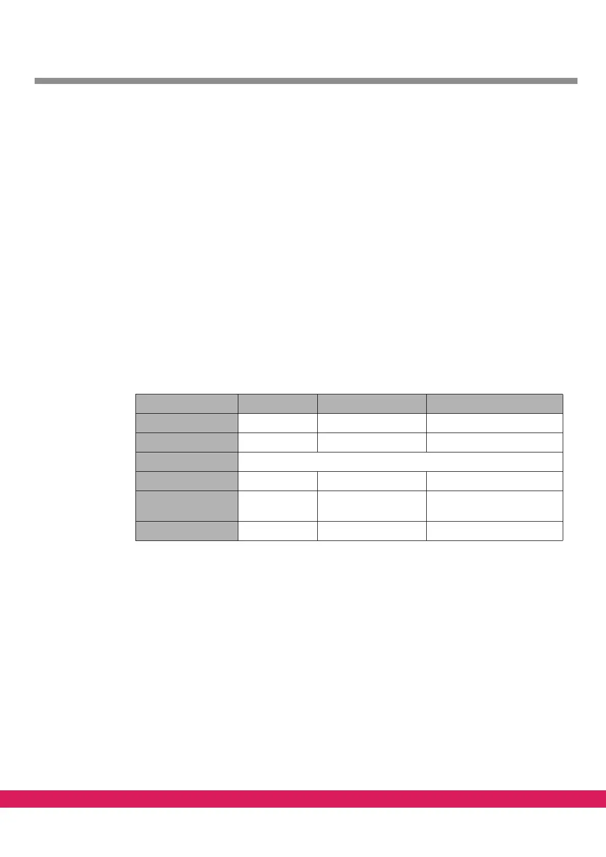
6.6.1 Example of synchronized axes at the CAN-Bus
The drive setup consists of three drives with the following characteristics
Tabelle 21:
Table 21: Example of synchronized axis, drive configuration
Drive 1 Drive 2 Drive 3
Axis number 0 1 1
CAN node address 8 7 3
CAN Baud rate 500 kB
Axis denomination C X (X’)
Type of axis Axis of rotation Linear axis synchronized axis to drive 2
with equal characteristics
Resolution pulses 4096 8192 as drive 2