55 / 97
Introduction Manual ENC66
eckelmann.de
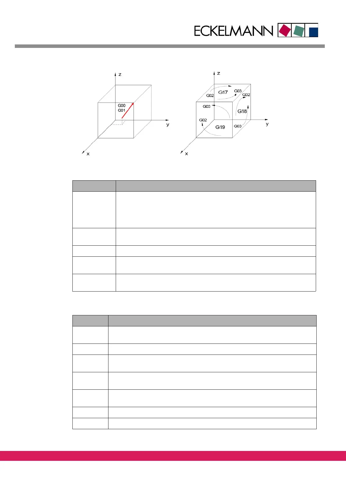
Abbildung 34:
Figure 34: Representation of a G function
Tab elle 28:
Table 28: Parameters for G00 and G01
Parameter Meaning
AXES Target point coordinates of the linear axes X, Y, Z, A, B, C, U, V, W x, y, z, a, b, c,
u,
v, w
Note: in a G-function, only the axes X, Y, Z, A
, B, C, U, V, W or the axes x, y, z, a,
b, c, u, v, w are to be used
D Max. path deviation in the t
arget point for an edge curving with the following
linear interpolation
R Radius with which the followin
g linear interpolation (G0, G1) is to be connected
F Rapid speed (G00) or feeding speed (G01) on the path (G31) or each axis (G30)
also for all following l
inear interpolations
E, L Selection of the feeding speed via
the number of revolutions (E) and the step
size (L) F=E*L.
Tab elle 29:
Parameter Meaning
AXES Target point coordinates of the three linear
master axes (default X,Y,Z), as well as
start and/or target point coordinates of the three rotative slave axes (Default A,B,C)
D Change of radius when the target point is reached
I Center point coordinate of the first master axis (X) or number of ad
ditional full cir-
cles
J Center point coordinate of the second master axis (Y) or number of additional full
circ
les
K Center point coordinate of the third master axi
s (Z) or number of additional full cir-
cles
R Interpolation radius
F Path speed
Table 29: Parameters for G02 and G03