Do you have a question about the ECKELMANN E-Control CNC and is the answer not in the manual?
Describes the composition of general notes in the manual, including icon, bar, and text.
Details the five parts of safety instructions and hazard warnings, including icons and warning levels.
Lists reference documents and technical descriptions for controllers, aiding further detail retrieval.
Compares the two operating modes of the controllers: Stand-Alone and With PC-HMI, detailing their characteristics.
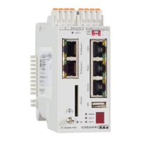
Explains the 7-segment indicator's display patterns during the controller's booting phase, indicating initialization steps.
Details the 7-segment indicator patterns that signal probable errors during the controller's booting phase.
Illustrates a typical system structure including the ENC66 controller, power supply, and I/O modules.
Describes the required cable and adapter for establishing a serial connection between the PC and the controller.
Outlines the need for an IP address for PC-controller communication via Ethernet, whether local or networked.
Explains how to use a terminal program for communication between PC and controller via serial interface.
Lists and describes important commands for interacting with the controller's monitor interface, such as dir, del, reboot, help.
Explains how to set the controller's IP address, subnet mask, and gateway using the `ipconf` command via the serial monitor interface.
Describes the initial state and procedure to access the controller's boot monitor for firmware updates via serial interface.
Explains the necessity of parameterizing drives both in the drive itself and within the controller using machine constants (MK).
Discusses how specified values for axes and CAN node addresses in machine constants relate to the controller's NC firmware capacity.
Lists and describes crucial machine constants (MK) required for configuring drives, categorized by setup and hardware configuration.
Covers machine constants for CANopen baud rate, interpolation cycles, speeds, acceleration/brake ramps, and damping time constants.
Describes synchronized and gantry axes, including compulsory coupling and master/slave axis designation.
Provides examples of synchronized axes setup via CAN-Bus and analog interface.
Explains G-functions used for defining geometric path conditions in axis operations, including their structure and examples.
Guides through the installation and startup process of the StdHMI software, including its usage modes.
Details modifying, checking, and jogging drives using machine constants within StdHMI.
Describes the StdHMI program editor's interface, including listing, input, and graphical display sections.
Provides a step-by-step guide for inputting a simple square contour program with rounded corners using the editor.
Covers exiting the StdHMI application and changing the user interface language between English and German.
Details how to modify the color settings of the StdHMI graphical display by editing the interpreter.ini file.
Identifies the necessary software package (ETOOLS PLC/2) and hardware modules required for PLC programming.
Introduces the process of configuring the controller as a prerequisite for generating PLC programs using ETOOLS PLC2.
Guides on locating and running the CNC Test sample PLC program stored on the ECKELMANN AG ftp-server or CD.
Explains the purpose and logic of key function blocks like START_STOP, RELEASE_SIGNAL_HANDLER, and M_FUNCTIONS.
Outlines the two connection options (serial, network) for loading programs into the controller via CoDeSys.
Outlines how to test CNC and PLC programs, mentioning machine constant settings for test modes.
Details the wiring requirements for controller inputs, specifically the emergency stop circuit and tool up/down inputs.
| Brand | ECKELMANN |
|---|---|
| Model | E-Control CNC |
| Category | Industrial Equipment |
| Language | English |