23 / 97
Introduction Manual ENC66
eckelmann.de
Abbildung 5:
EExC66
WDOG
LED2
LED1
USB Ethernet RS232 CAN2
CAN3CAN4SD-Card
1
2
4
3
CAN
Term
SD
WD 2WD 1 C_ GD C_H C_L PE
E-Control ExC66 with power
supply and LBM IO modules
5V
24V
5A
24V 24V 0V 0V
ELBM
PWR04
24V 24V 0V 0V
ELBM
DIM16
I 5
I 4
I 3
I 2
I 1
24V
LIFE
I 6
I 7
I 8
0V
I 13
I 12
I 11
I 10
I 9
24V
I 14
I 15
I 16
0V
24V 24V 0V 0V
ELBM
DIM16
I 5
I 4
I 3
I 2
I 1
24V
LIFE
I 6
I 7
I 8
0V
I 13
I 12
I 11
I 10
I 9
24V
I 14
I 15
I 16
0V
E
n
c
o
d
e
r
D
i
g
it
a
l
IN
/
A
n
a
l
o
g
O
U
T
24V 24V 0V 0V
ELBM
ARI01
I4
I3
I2
I1
REL
REL
LIFE
DCOM
AO1
ACOM
24 V0V
24V 24V 0V 0V
ELBM
AIO22
AI2+
0V
24V
SHLD
AI1-
AI1+
LIFE
AI2-
SHLD
24V
0V
OCOM
AO1
SHLD
10V
10V
PE
SHLD
AO2
OCOM
SHLD
24V 24V 0V 0V
ELBM
SER02
LIFE
CAN1
Watchdog
CAN3
CAN4
CAN2
Ethernet
RS-232
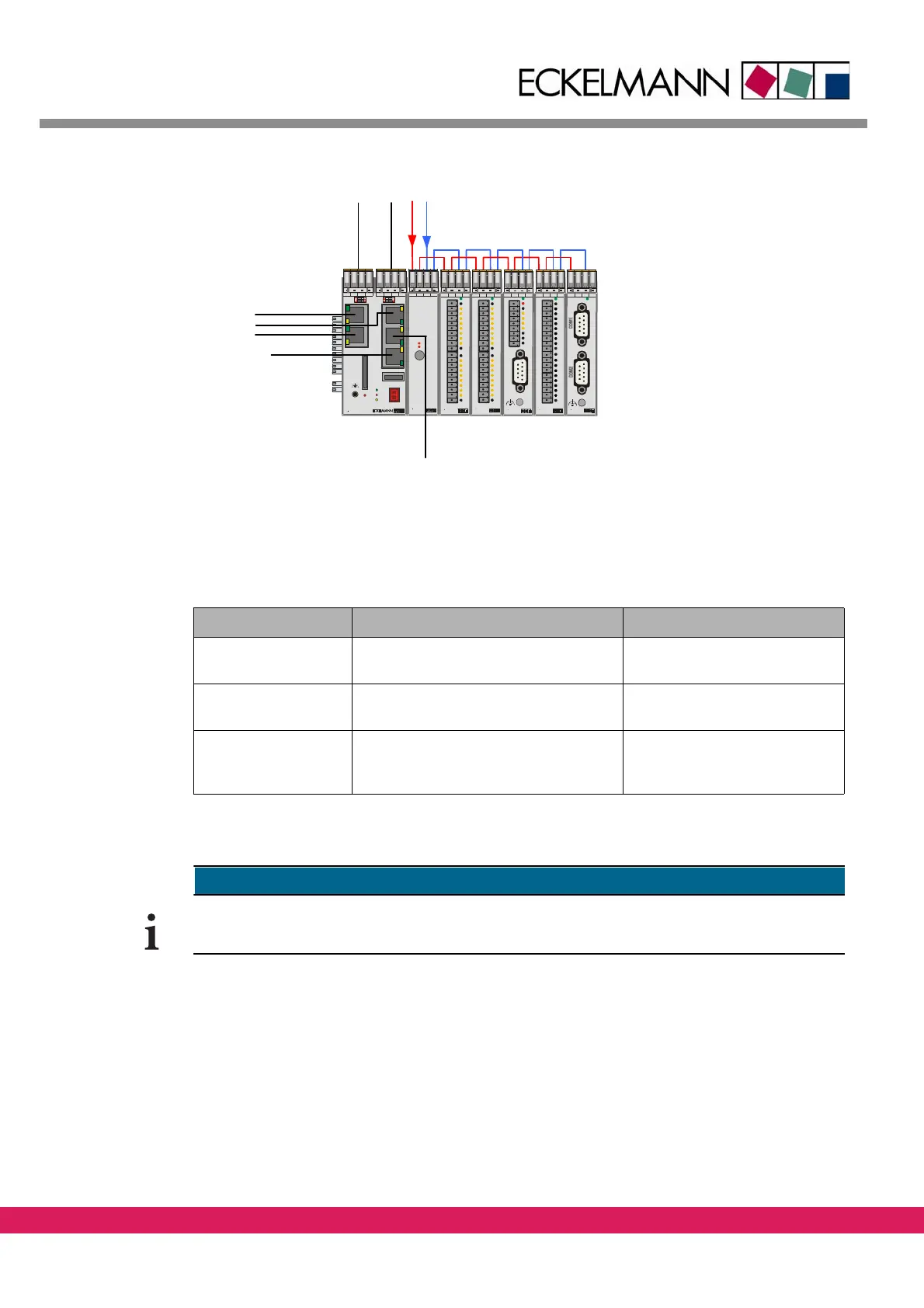
Figure 5: Wiring of an ENC66 controller
The connection of the controller and a PC can be made in three different ways:
Tab elle 14:
Table 14: Type of connections between controller and PC
Type of connection Connection via IP address of the controller
Serial connection Serial interface of the PC (COM port)
with ze
ro-modem cable
Setting is not required
Local connection via
Ethernet
Direct Ethernet crossover patch cable
STP
Cat5 between controller and PC
Setting is required
Network via Ethernet An Ethernet patch cabl
e STP Cat5 each
from controller and PC to the network
(RJ45)
Setting is required
x
Connecting to a controller with a terminal program can be done via the serial port or eth-
ernet.