24 / 97
Abbildung 6:
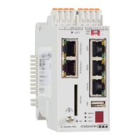
Serial connection
Local connection via
ethernet
EExC66
WDOG
LED2
LED1
USB Ethernet RS232 CAN2
CAN3CAN4SD-Card
1
2
4
3
CAN
Term
SD
WD 2 WD 1 C_GD C_H C_L PE
EExC66
WDOG
LED2
LED1
USB Ethernet RS232 CAN2
CAN3CAN4SD-Card
1
2
4
3
CAN
Term
SD
WD 2 WD 1 C_GD C_H C_L PE
EExC66
WDOG
LED2
LED1
USB Ethernet RS232 CAN2
CAN3CAN4SD-Card
1
2
4
3
CAN
Term
SD
WD 2 WD 1 C_G D C_ H C_L PE
Network
Figure 6: Connection controller <--> PC
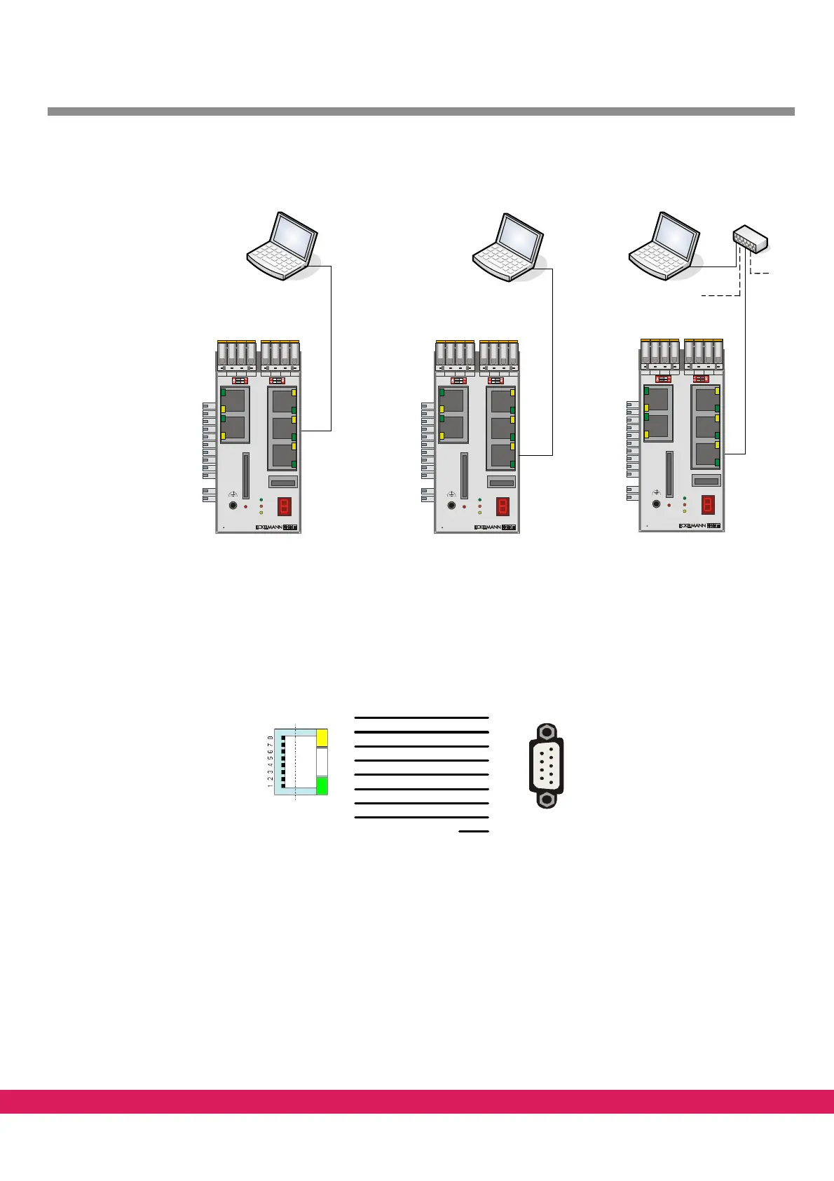
2.3 Serial connection
For a serial connection between the PC and the controller a zero-modem cable and the fol-
lowing adaptor (RJ-45 connector to 9-pole D-
Sub male plug) are required.
Abbildung 7:
Pin 8: RTS
Pin 7: CTS
Pin 6: TX
Pin 5: RX
Pin 4: GND
Pin 3: DTR
Pin 2: DCD
Pin 1: DSR
1
2
3
4
5
6
7
8
6
1
4
5
2
3
8
7
9
nc
ExC66 PC
Figure 7: Connecting cable controller <--> PC
2.4 Connection via Ethernet
For the communication between the PC and the controller, the controllers requires and in-
dividual (but specified) IP address in the network. This is also valid in case of a local connec-
tion.
This IP address can either be freely assigned (if no other device is connected with the net-
work) or the address is preset and managed by a network administrator