91 / 97
Introduction Manual ENC66
eckelmann.de
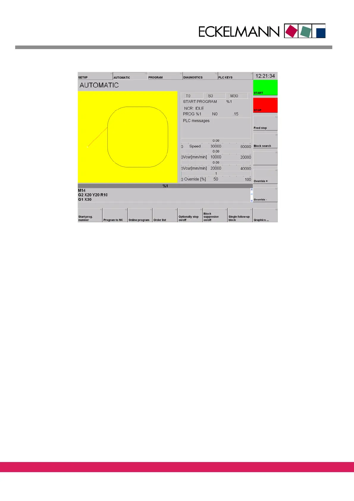
Abbildung 65:
Figure 65: Loaded DIN program in the StdHMI
Upon correct loading of the PLC and CNC program, a mark follows the circular contour.
The output „Lower tool“ is set and reset in
compliance with the called M-function.
11.4 Error messages of the CNC program
If one of the two inputs is not set on 24V in time, the program stops and the following error
message is displayed in a red box.
This error message is generated upon elapsing of the timer of 5 s via the function SPSERROR
i
n the module M_FUNCTIONS. The text pertinent to the error number is included in the file
„sps_fehl.db“ (English version: „sps_erro.db“). This file is stored in the directory „cfg“ of
the StdHMI.
The screen displayed below indicates an er
ror of the controller (2), of the module PLC pro-
gram (10) with the error number 400 (F_TOOL_UP_KI).
Therefore, for a correct error mes-
sage, an error number 2.10.400 with the res
pective text is to be entered in file
„sps_fehl.db“.