76 / 97
Abbildung 51:
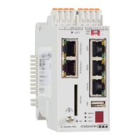
Figure 51: The added LBM DOM16 module in the PLC configuration
The process image of the ENC66 is organized on the basis of words. So the entries for the
new module have to be changed in this manner. The module uses one input and one output
word.
Abbildung 52:
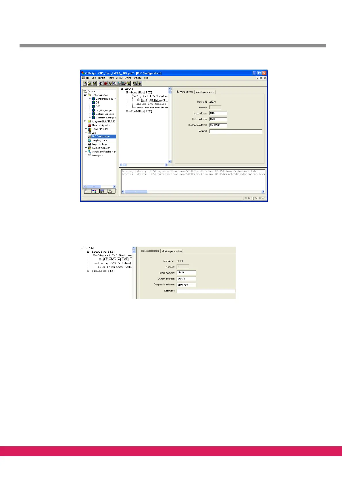
Figure 52: Byte addresses changed to word addresses
A diagnostic of the module condition from the PLC program is possible by means of the di-
agnostic address to be specified in the controller configuration for each module. You can
find out the follo
wing states of the modules:
• Operation state of the modules
• Availability of the 24V process voltage
• State of the watchdog triggering via the local b
us. The bus communication prevents
the watchdog from triggering. Otherwise the outputs are switched off.
• Failure of the reference voltage of analog modules
• Detecting short circuits for digital output modules
Details for the diagnostic address can be found in /9/.