•
•
•
•
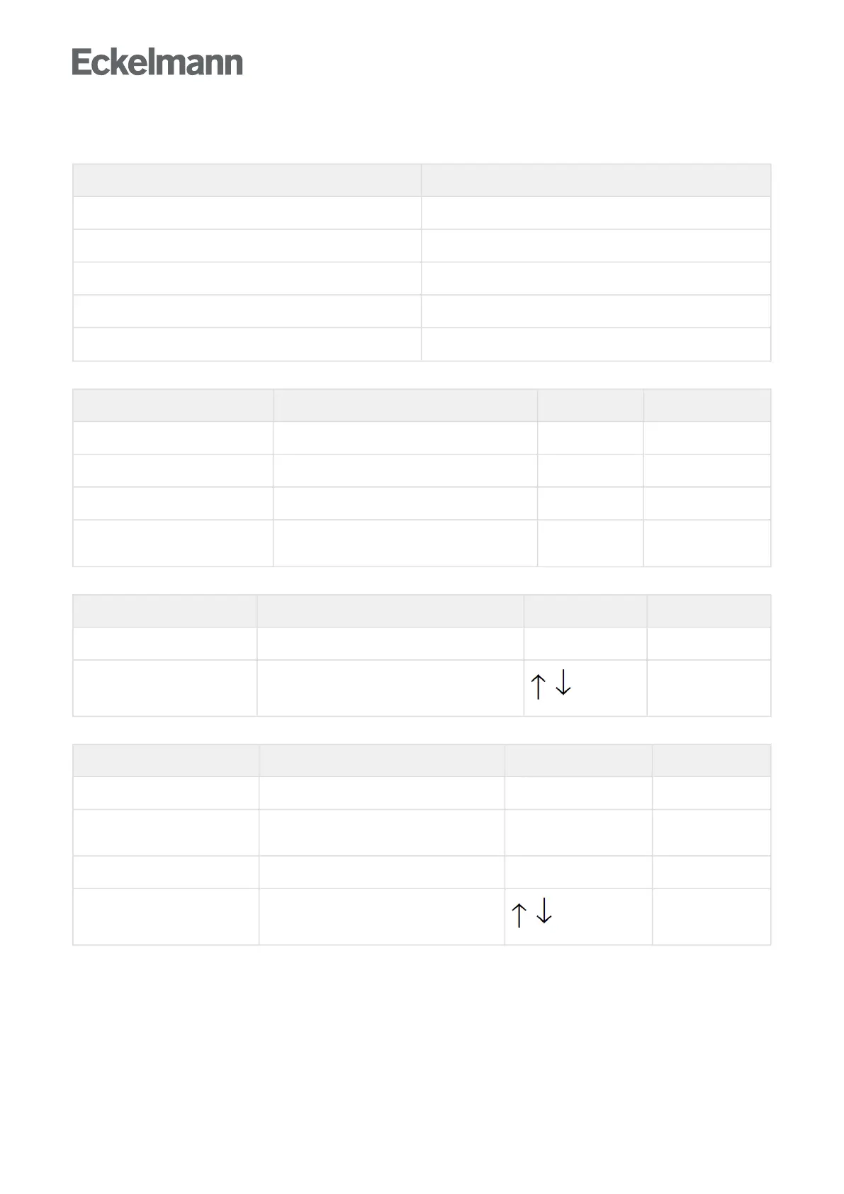
Menu 6-2 - Controller
REGLER POS: XXXXX
1 Type and version Continue to menu 6-2-1
2 Temperature display Continue to menu 6-2-2
3 Alarm delay Continue to menu 6-2-3
4 230 V inputs Continue to menu 6-2-4
5 Sensor type Continue to menu 6-2-5
Menu 6-2-1 Type and version
VERSION POS: XXXXX Input Default
ReglertypXXXXXXX Controller type that is set using the DIP switch S3 – UA111
Software Vers.:XXXX Software version of the case controller – x.yy
Gerät Nr:XXXXXX Serial number of the case controller –
Master/Sl. ModeXXX Synchronised defrost in the master / slave mode
(ON/OFF)
–
Menu 6-2-2 Temperature display
ANZEIGE POS: XXXXX Input Default
OffsetXX K Offset for the display of the temperature -10..10 0K
AlarmsymbolX Display of the alarm sysmbol in the temperature
display of the BT30
, , (Y, N)
N
Menu 6-2-3 Alarm delay
ALARMVERZ. ID: XXXXX Input Default
FühlerbruchXX m Alarm delay for sensor fault 0..30 15 min
Über/Unter TmpXX m Alarm delay for overtemperature / low
temperature
0..120 60 min
keine AbtauungXX h Alarm delay for no defrost --, 2..168 24 h
SelbsthaltungX NO: Automatic reset of non-transient alarms.
YES: Alarms must be reset manually.
, , (Y/N)
N