•
•
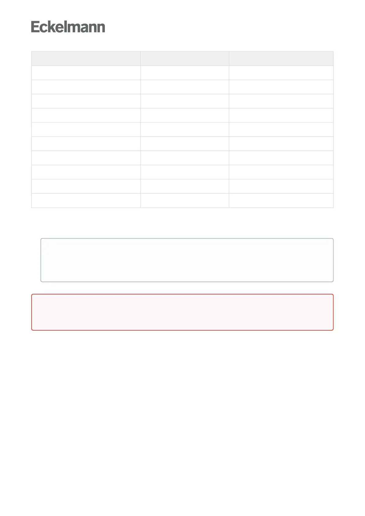
Controller type Required sensors Allocated defrost relay
UA 111 / UA 141 R2.1 R2.2 Defrost relay 1
R2.3 R2.4 Defrost relay 2
UA 121 R1.1 R1.2 Defrost relay 1
R1.3 R1.4 Defrost relay 2
UA 131 / UA 131 DD R1.1 Defrost relay 1
R1.2 Defrost relay 2
R1.3 Defrost relay 3
R1.4 Defrost relay 4
UR 141 NK(NT) / UR 141 TK(LT) R1.1 R1.2 Defrost relay 1
R1.3 R1.4 Defrost relay 2
Defrost initiation
Defrostingcanbeinitiatedbyfourmethods:
By internal clock (not UA 131 DD)
Using an external timerviadigitalinputD11/D12(factorysetting).
Afurtherdefrostcanonlybeinitiatedaftertheendofthesafedefrosttime(defrostparameters),
even when the defrost has already been terminated via the evaporator temperatures. Defrosting
should be timed to take place between 0200 and 0300 hours where possible so as to avoid
problems of missed or duplicated defrosting when changing to or from daylight saving time.
Warning – hazardous electrical voltage! Danger of electric shock! BEFOREconnectingand
disconnecting it must be checked that the 230 V AC digital inputs are off load! The controller and
connected voltage carrying components remain supplied with power!