Parameter List and Menu Structure of VS 300
127
Doku-Version 2.05 - Firmware 2.10 - 15. September 2017
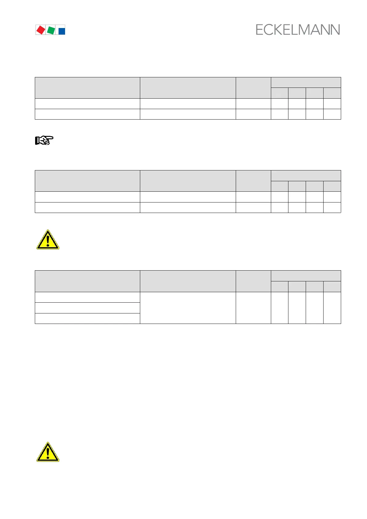
S Screen 3-1-c Sensor Control Loop 1
TRANSD.CL1 POS: XXXXX Input
Default
NT LT HP Dim.
px 4mA XXX b Set sensor parameter: Pressure at 4mA 0,0..2,0 0,0 0,0 1,0 bar
px 20mA xxx b Set sensor parameter: Pressure at 20mA 8,0..60,0 10,0 10,0 75,0 bar
p
x
equivalent to either p
0
or p
c
(depending on expansion stage and configuration).
S Screen 3-1-d Select Control Type for Control Loop 1
CONT TYPE POS: XXXXX Entry
Default
NT LT HP Dim.
Pressure √ Default √ √ √ √ -
Consumer √ - - - -
Faulty parameter setting can cause severe impairment of function.
S Screen 3-1-e Control Loop 2 - Compressors/Fans
CL2-COMP/COND. POS: XXXXX Entry
Default
NT LT HP Dim.
Stage 1
1)
XXX
Shows only relay/control stages allocated
to Control Loop 1
↑ , ↓
(ON/OFF)
ON ON ON -
...
Stage 12
1)
XXX
1)
0 to 4/8/12 depending on expansion stage and configuration (see section 3 Function - System
Configuration/Allocation of Relay/Control Stages).
S Screen 3-1-f Select refrigerant Control Loop 2
See Screen 3-1-b.
S Screen 3-1-g Sensor Control Loop 2
See Screen 3-1-c.
S Screen 3-1-h Select Control Type for Control Loop 2
See Screen 3-1-d.
Faulty parameter setting can cause severe impairment of function.