Parameter List and Menu Structure of VS 300
128
Doku-Version 2.05 - Firmware 2.10 - 15. September 2017
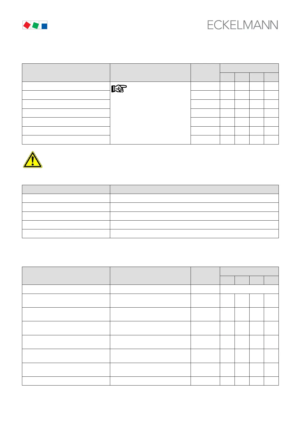
S Screen 3-1-i Controller configuration - only shown in Superuser mode!
Config POS: XXXXX Entry
Default
NT LT HP Dim.
LTLT
Controller configuration must be
made prior to making individual pa
rameter setting, as first start is per
formed when configuration is chan
ged.
√ - - - -
LTNT √ - - - -
LTHP √ - - - -
NTNT √ - - - -
NTHP √ - - - -
HPHP √ - - - -
NTLT √ - - - -
On first start, default values are loaded for all parameters and all archives (alarms and operating
data, e.g. run times, starts, activity) are deleted!
S Menu 3-2 Setpoints for CL1 control
SETPOINTS POS: XXXXX
1 Control type Next: Screen 3-2-1
2 to adjustment CL1 Next: Screen 3-2-2 1)
3 Load times CL1 Next: Screen 3-2-3
4 LP/HP cont. day CL1 Next: Screen 3-2-4
5 LP/HP cont.night CL1 Next: Screen 3-2-5
1)
Only shown when control loop is configured as LP controller.
S Menu 3-2-1 Control Type Control Loope 1
CL1-CONT POS: XXXXX Entry
Default
NT LT HP Dim.
Control type → Control type selection list CL1 → Next: Screen 3-2-1-a
Min.speed XXX % Minimum speed of variable-speed com
pressor/fan with continuous control
1)
0 - 50 0 0 0 %
Adjust diff. XX Speed controller adjusting speed (I ac
tion)
1)
-15 - 15 0 0 0 -
t-max SpeedC. XX °C Max. temperature in CL1 with speed con
trol (bypass actuation)
1)
-35 - 45 -8 -25 40 °C
Cycle time BLR XXX Cycle time for base load rotation/fan pro
tection CL1
5 - 720 or
--
45 45 45 min
On time cond. X Actuation mode: By run time (Y) or se
quential actuation (N) in CL1
2)
↑ , ↓
(N/Y)
Y Y Y -
Max. HR CL1 XX °C Max. temperature in heat recovery mode
2)
30 - 50 - - 46 °C
HR dif. CL1 XX K Control hysteresis HR mode
2)
1 - 10 - - 4 K
1)
Only shown when CL control type is speed or combined controller - Screen 3-2-1-a.
2)
Only shown when control loop is configured as HP controller.