Parameter List and Menu Structure of VS 300
131
Doku-Version 2.05 - Firmware 2.10 - 15. September 2017
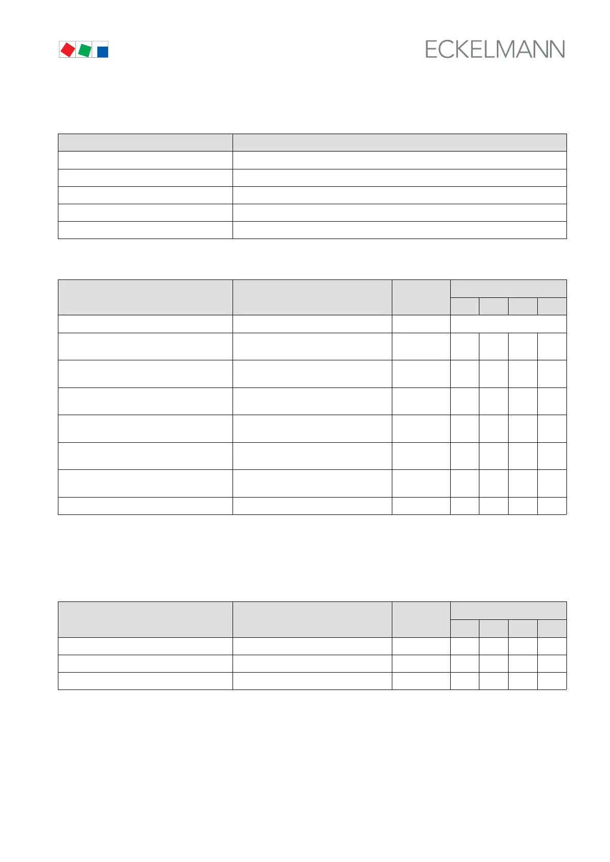
S Menu 3-3 Setpoints for CL2 Control
SETPOINTS POS: XXXXX
1 Control type Next: Screen 3-3-1
2 to adjustment CL2 Next: Screen 3-3-2
3 Load times CL2 Next: Screen 3-3-3
4 LP/HP cont. day CL2 Next: Screen 3-3-4
5 LP/HP cont.night CL2 Next: Screen 3-3-5
S Menu 3-3-1 Control Type Control Loop 2
CL2-COMP/COND POS: XXXXX Entry
Default
NT LT HP Dim.
Contorl Type → Selection list for control type CL2 → Next: Screen 3-3-1-a
Min.speed XXX % Minimum speed of variable-speed con
denser/fan with continuous control
1)
0 - 50 0 0 0 %
Adjust diff. XX Speed controller adjusting speed (I ac
tion)
1)
-15 - 15 0 0 0 -
t-max SpeedC. XX °C Max. temperature in CL2 with speed con
trol (bypass actuation)
1)
-35 - 45 -8 -25 40 °C
Cycle time BLR XXX Cycle time for base load rotation/fan pro
tection CL2
5 - 720 or -- 45 45 45 min
On time cond. X Actuation mode: By run time (Y) or se
quential actuation (N) in CL1
2)
↑ , ↓
(N/Y)
Y Y Y -
Max. HR CL2 XX °C Max. temperature in heat recovery mode
2)
30 - 50 - - 46 °C
HR dif. CL2 XX K Control hysteresis HR mode
2)
1 - 10 - - 4 K
1)
Only shown when CL control type is speed or combined controller - Screen 3-2-1-a.
2)
Only shown when control loop is configured as HP controller.
S Screen 3-3-1-a Control Type Control Loop 2
CONTROL POS: XXXXX Entry
Default
NT LT HP Dim.
Step controller √ Select control type in CL2 √ √ √ √ -
Speed controller √ - - - -
Combi controller √ - - - -