Parameter List and Menu Structure of VS 300
132
Doku-Version 2.05 - Firmware 2.10 - 15. September 2017
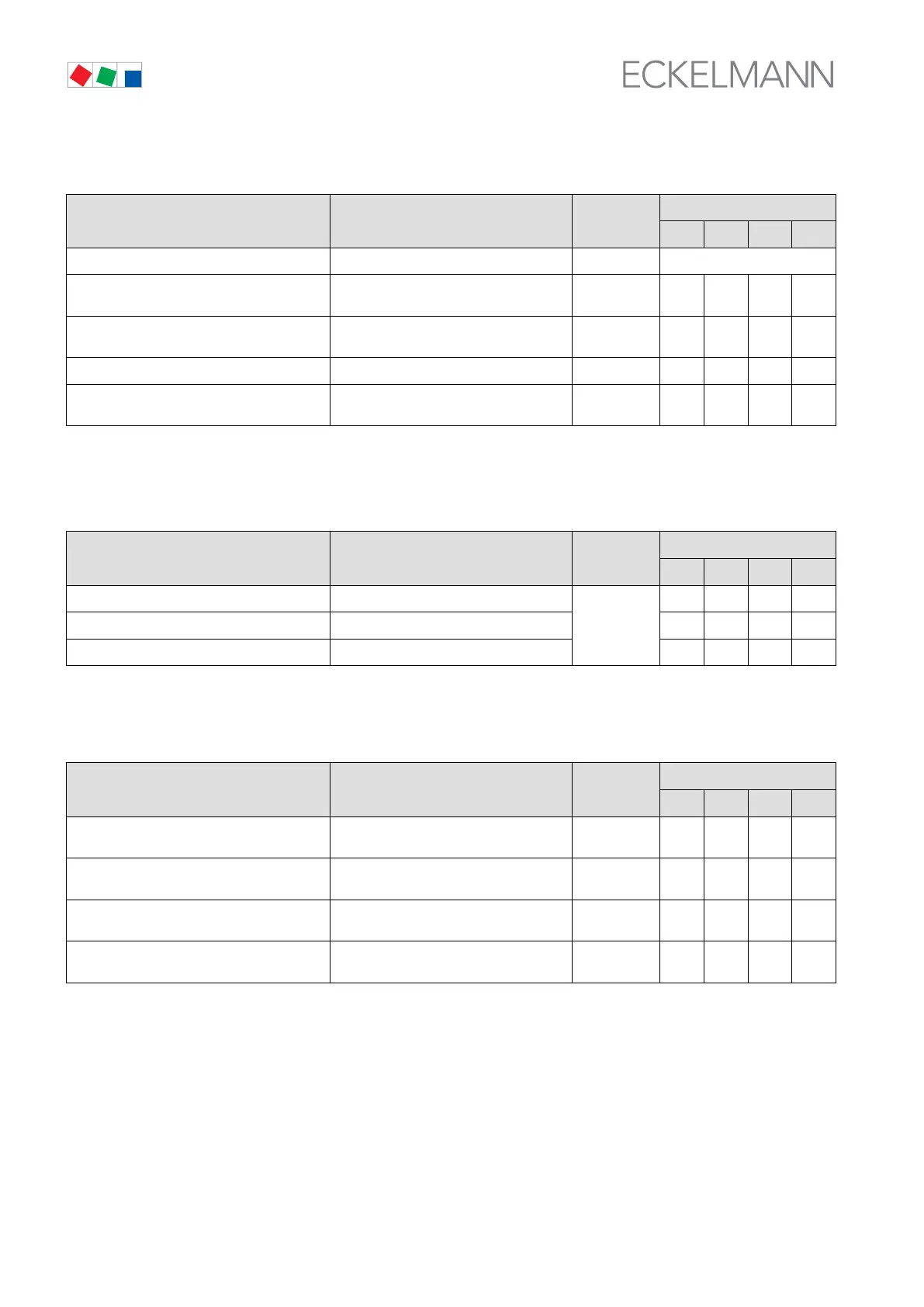
S Menu 3-3-2 to adjustment control loop 2
to adjust. POS: XXXXX Entry
Default
NT LT HP Dim.
to-Schiebung → Select input quantity for to shift → See Screen 3-3-2-a
Max.LoadLevel XXX % Enter maximum load level for suction
pressure shift
70..100 100 100 - %
Max.LoadLevel XXX % Enter minimum load level for suction pres
sure shift
10..60 50 50 - %
Increment XX.X K Enter increment for suction pressure shift 0,0..10,0 1,0 1,0 - K
Interval XX m Enter time interval for suction pressure
shift
1..20 5 5 - min
Only shown when control loop is configured as LP controller.
S Screen 3-3-2-a to adjustment control loop 1
to adjust. POS: XXXXX Entry
Default
NT LT HP Dim.
none √ to shift deactivated
√
√ √ - -
Room temp. √ to shift by room temperature - - - -
Consumer to shift by refrigeration point - - - -
Screen is only shown when control loop is configured as LP controller.
S Menu 3-3-3 Actuating Times Control Loop 2
LOAD-TIMES POS: XXXXX Entry
Default
NT LT HP Dim.
Bas. load time XXX s Basic load time for compressor/fan stages
in CL2
3 - 250 30 60 10 s
Vari.load time XXX s Variable load time for compressor/fan sta
ges in CL2
3 - 250 250 250 30 s
Bas. unlo.time XXX s Basic unload time for compressor/fan sta
ges in CL2
3 - 250 10 10 20 s
Vari.unlo.time XXX s Variable unload time for compressor/fan
stages in CL2
3 - 250 30 20 30 s