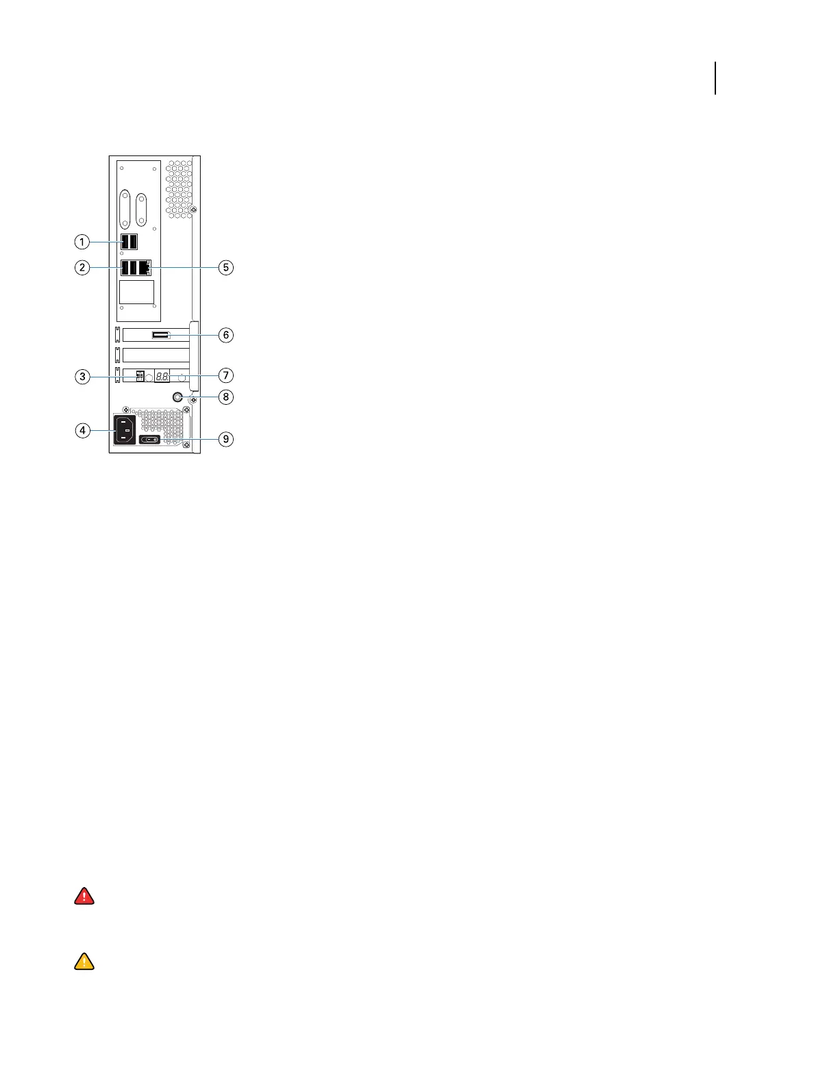
Figure 2: Fiery ES connector panel
1 Type A USB2.0 ports (x2)
2 Type A USB3.0 ports (x2)
3 Service switch
4 Power connector
5 Network port (10/100/1000 BaseT)
6 Printer interface port
7 LED display
8 Power button
9 Power switch
I: Power ON
O: Power OFF
Steps to integrate the Fiery ES into your network
This procedure provides an overview of the steps required to integrate the Fiery ES into your network and print
environment.
Warning: Ensure all cables remain routed to prevent trip hazards and to prevent accidental disconnection or
damage. Ensure that the cables are not compressed, pinched, or bent at a sharp angle. Damaged cables can
result in electric shock to personnel, in addition to faulty operation of the equipment.
Caution: Use caution and correct ergonomic procedures if it is necessary to lift or move the Fiery ES or
connected equipment.
Configuration and Setup
Integrating the Fiery ES into your network
19