Titanium Interfaces User Guide
Local and Core Feedback Mode Where:
F
PFD
= F
IN
/ N
F
VCO
= (F
PFD
x M x O x C
FBK
)
(8)
F
PLL
= F
VCO
/ O
F
OUT
= (F
IN
x M x C
FBK
) / (N x C)
F
VCO
is the voltage control oscillator frequency
F
PLL
is the post-divider PLL VCO frequency
F
OUT
is the output clock frequency
F
IN
is the reference clock frequency
F
PFD
is the phase frequency detector input frequency
O is the post-divider counter
C is the output divider
Note: Refer to the PLL Timing and AC Characteristics for F
VCO
, F
OUT
. F
IN
, F
PLL
, and F
PFD
values.
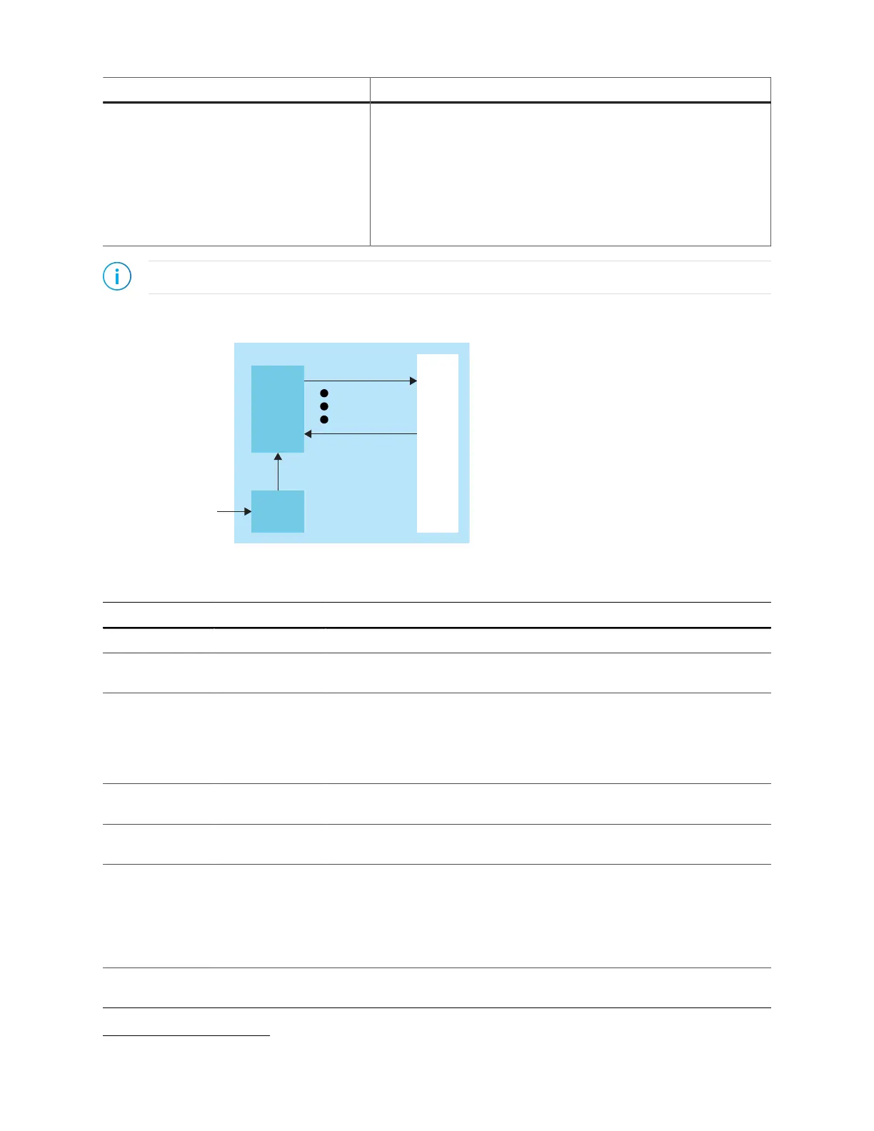
Figure 49: PLL Interface Block Diagram
Table 79: PLL Signals (Interface to FPGA Fabric)
Signal Direction Description
CLKIN[3:0] Input Reference clocks driven by I/O pads or core clock tree.
CLKSEL[1:0] Input You can dynamically select the reference clock from one of the clock in
pins.
RSTN Input Active-low PLL reset signal. When asserted, this signal resets the PLL;
when de-asserted, it enables the PLL. Connect this signal in your design to
power up or reset the PLL. Assert the RSTN pin for a minimum pulse of 10
ns to reset the PLL.
Assert RSTN when dynamically changing the selected PLL reference clock.
FBK Input Connect to a clock out interface pin when the PLL is in core feedback
mode.
IOFBK Input Connect to a clock out interface pin when the PLL is in external I/O
feedback mode.
CLKOUT0
CLKOUT1
CLKOUT2
CLKOUT3
CLKOUT4
Output PLL output. You can route these signals as input clocks to the core's GCLK
network.
You can use CLKOUT0 only for clocks with a maximum frequency of 4x
(integer) of the reference clock. If all your system clocks do not fall within
this range, you should dedicate one unused clock for CLKOUT0.
LOCKED Output Goes high when PLL achieves lock; goes low when a loss of lock is
detected. Connect this signal in your design to monitor the lock status.
(8)
(M x O x C
FBK
) must be ≤ 255.
www.efinixinc.com 122