ES910.3-A - User’s Guide 20
ETAS Hardware Description
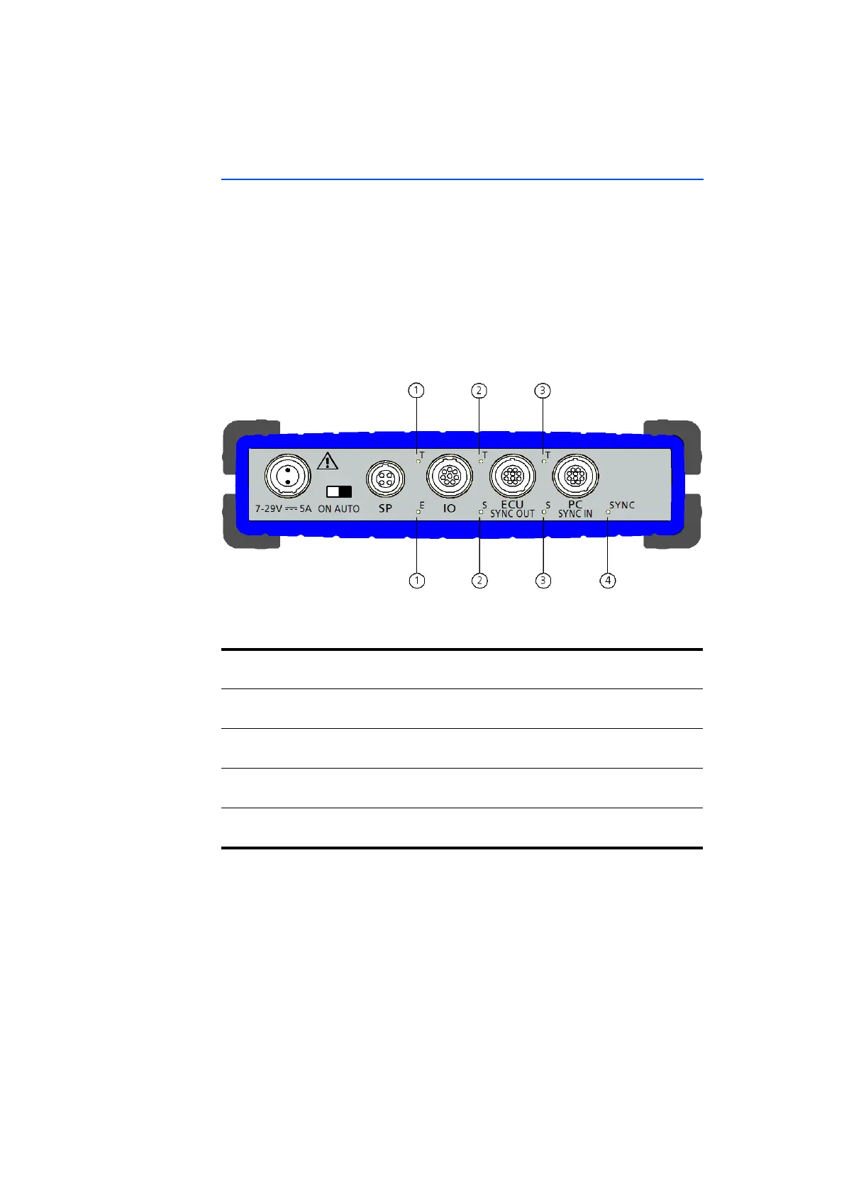
3.3.2 Back Panel
The following interfaces are on the back panel of the ES910.3-A:
• 6 ... 32V DC (power supply)
• ON/AUTO switch
• SP (Service Port)
• IO (interface for ES4xx/ES63x/ES93x modules or EtherCAT automation
bus)
• ECU SYNC OUT (ECU or iLinkRT
TM
interface)
• PC SYNC IN (Ethernet interface to the PC)
Fig. 3-3 ES910.3-A Back Panel
LEDs are assigned to some interfaces of the module:
No. in Fig. 3-3
(Name of LED)
Assignment Display Function
1
(T, 2E)
IO Communication at the IO interface
(see chapter 3.4.4 on page 23)
2
(T, S)
ECU Communication at the ECU interface
(see chapter 3.4.4 on page 23)
3
(T, S)
PC Communication at the PC interface
(see chapter 3.4.4 on page 23)
4
(SYNC)
Module Synchronization state of the module (see
chapter 3.4.3 on page 22)