ES910.3-A - User’s Guide 29
ETAS Functional Description
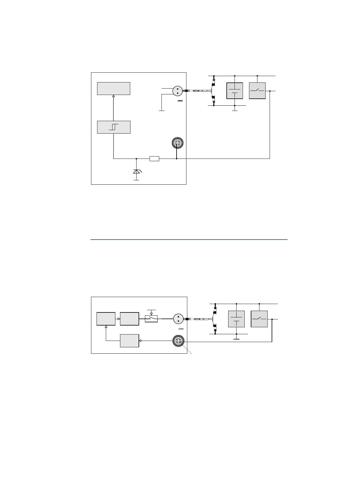
Fig. 4-5 “Manual Trigger” Function with Terminal 15
The state of the button connected to the two pins can also be queried from the
Rapid Prototyping model (Polling Mode).
The necessary minimum pulse width of the initiating trigger signal can be config-
ured in the calibration software.
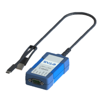
4.6.2 “Wake Up Control” Pin
The ES910.3-A can be activated at the "Wake Up" pin of the Service interface
(SP) when connected to the operating voltage. It is possible to switch between
"Standby" and "On" if the ON/AUTO switch is switched to "AUTO" (see chap-
ter 4.3.2 on page 26).
Usually, the “Wake Up” pin is connected to the signal of terminal 15. The power
supply of the ES910.3-A is activated when UBATT is applied at terminal 15.
Fig. 4-6 Connecting the Wake Up Pin to Terminal 15
The voltage range at the “Wake Up Control” pin of the Service Port corresponds
to the operating voltage range of the ES910.3-A (7 V to 29 V direct voltage).
Interfering signals pending at the “Wake Up Control” pin of the Service Port are
filtered out. For more technical data, refer to the chapter 7.7.7 on page 84.
15
IgnitionKey
ES910.3‐A
7..29V
DC
Cable
CBP120
or
CBP1205
IRQ
UBATT
GND
Pin2
TRIGIN‐
CostumizedControlCable
SP
R
Simulation
Processor
GND
UBATT
Pin3
“Wake‐UpControl“
Wake‐Up
&Standby
Controller
ONAUTO
SP
ES910.3‐A
7..29V
DC
Power
Supply
Glitch
Filter
CustomizedControlCable
Cable
CBP120
or
CBP1205
UBATT
15
GND
IgnitionKey