ES910.3-A - User’s Guide 45
ETAS Getting Started
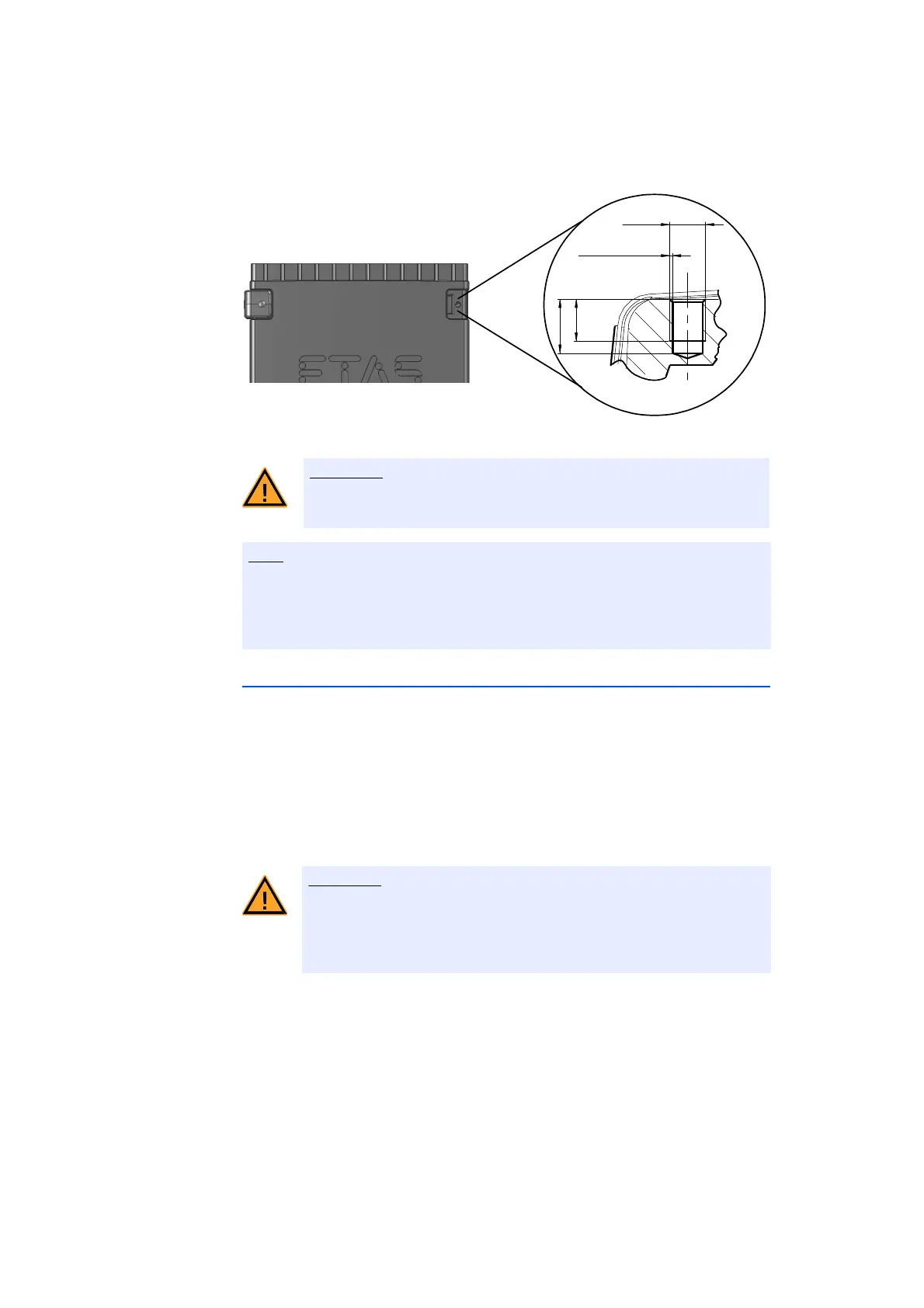
Fig. 5-3 Tapped blind hole
5.3.2 Connecting Several Modules Mechanically
As ETAS system housing was used, the ES910.3-A can also be connected to
modules of the ETAS compact line (ES59x, ES6xx, ES930) providing certain con-
ditions are adhered to (see chapter 5.2.2 on page 43). These can be combined
easily using the T-Brackets provided to form larger blocks.
ES910.3-A modules can only be connected vertically to other modules.
If the ES910.3-A is to be connected with modules of the ETAS compact line, the
latter must not be positioned to the side of the ES910.3-A as this would mean
insufficient exchange of heat.
You can attach a further module of the ETAS compact line under the ES910.3-A.
Just remove the four plastic feet on each of the relevant device sides and attach
the T-Brackets provided in their place.
The electronic can be damaged or destroyed!
Do not rework the threaded hole.
Use excluding M3 cylinder screws and fastening the module onto your carrier
system with a max. torque of 0.8 Nm.
The max. length of engagement into the tapped blind hole of housing is 3 mm
(see Fig. 5-3 on page 45).
Heat concentration on the long sides of the module.
The electronics can be damaged due to overheating.
Do not cover ventilation slits when setting up, assembling or connect-
ing with other modules. Adhere to the minimum distance at the sides.
M3
0.25 x 45°
3.5
min
4.5 max