ES910.3-A - User’s Guide 21
ETAS Hardware Description
3.4 Indicators
3.4.1 Flash Codes
The ES910.3-A is equipped with LEDs, which indicate the operational and func-
tional state of the module, as well as with LEDs which display the function of
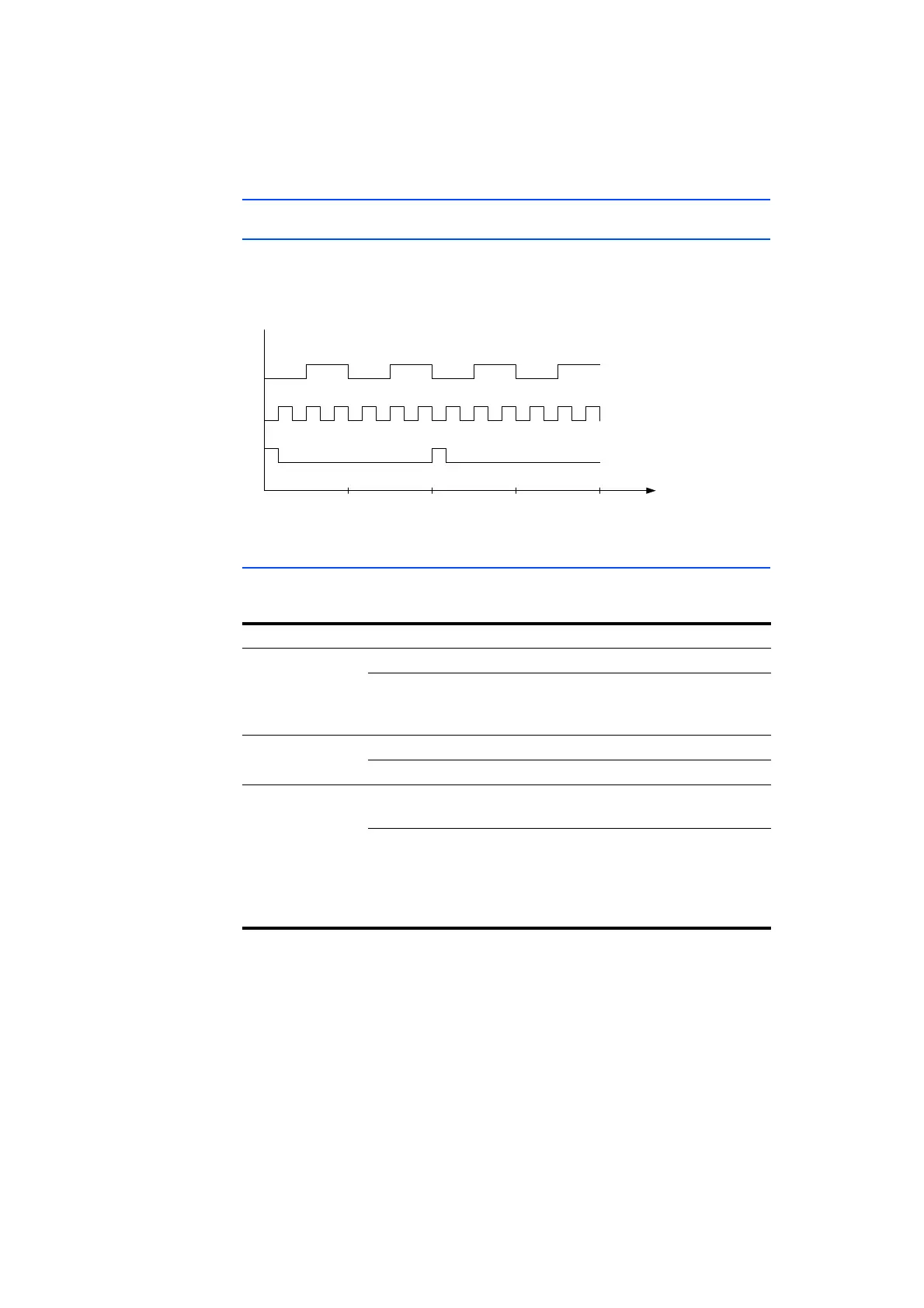
individual interfaces. The following flash codes are used for the LEDs:
Fig. 3-4 Flash Codes of the Indicators
3.4.2 ES910.3-A Operational State
Four LEDs can be found on the front panel of the ES910.3-A. They indicate the
following operational states:
LED Display Operational State
ON Green The unit is powered on.
Green, flashing
(Flash code 3)
The automatic power on/off of the
power supply is enabled and the device is
on “Standby”.
TX Yellow Data is being transferred.
Off No data transfer
ER Red Device is currently booting or booting
was unsuccessful.
Red, flashing
(Flash code 1)
Firmware update is being executed or
internal device software error (an error
file exists and can be called up in the web
interface of ES910.3-A and mailed to the
Technical Support)
1342 t (s)
LED Flash Co de 1
On
Off
Off
Off
On
On
LED
LED Flash Co de 2
LED Flash Co de 3