ES910.3-A - User’s Guide 28
ETAS Functional Description
4.6 Service Interface (SP)
The Service interface of the ES910.3-A is routed to a 4-pin SP connector (Lemo
socket) on the back panel of the device. Two connector pins are used for the
“Manual Trigger” function and one for the “Wake Up Power” function.
4.6.1 “Manual Trigger” Function
The “Manual Trigger” function at the two trigger pins of the Service Port (SP) of
the ES910.3-A can be used for different applications:
• realization of the emergency shutdown function after the emergency
shutdown button has been pressed or
• realization of power-on/initialization sequences after terminal 15 (Kl.15)
has been pressed.
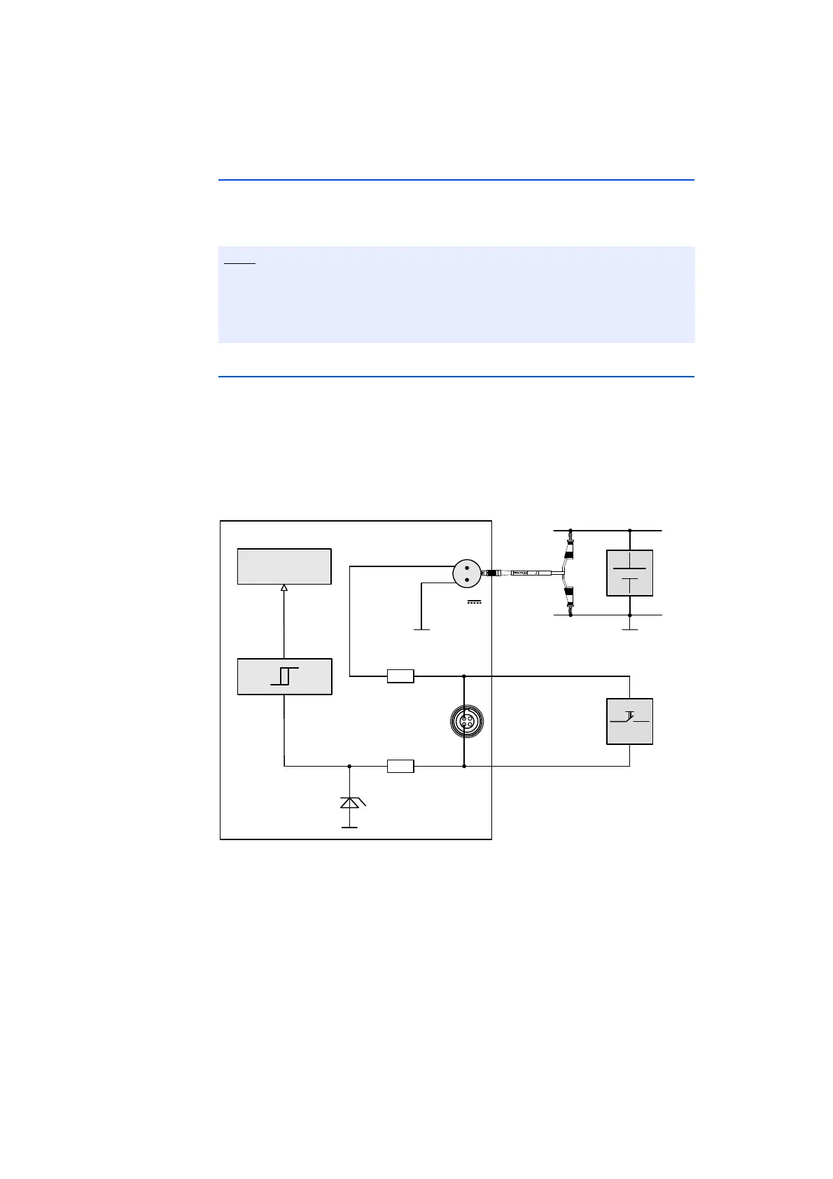
Fig. 4-4 “Manual Trigger” Function with Button between Pin 1 and Pin 2
If, for example, you install a button between the two trigger pins, changes in
button status are interpreted as a trigger event. Pressing the button generates an
interrupt for starting customized scenarios configured in the Rapid Prototyping
calibration software.
The cable for using the ES910.3-A “Manual Trigger” and “Wake Up” functions
has to be customized by the customer (see chapter 7.7.7 on page 84). The
necessary connector is not part of the delivery scope or accessories of the
ES910.3-A.
ES910.3‐A
7..29V
DC
Cable
CBP120
or
CBP1205
IRQ
UBATT
GND
Pin2
TRIGIN‐
CostumizedControlCable
Pin1
TRIGIN+
SP
R
R
Simulation
Processor
GND
UBATT