ES910.3-A - User’s Guide 38
ETAS Functional Description
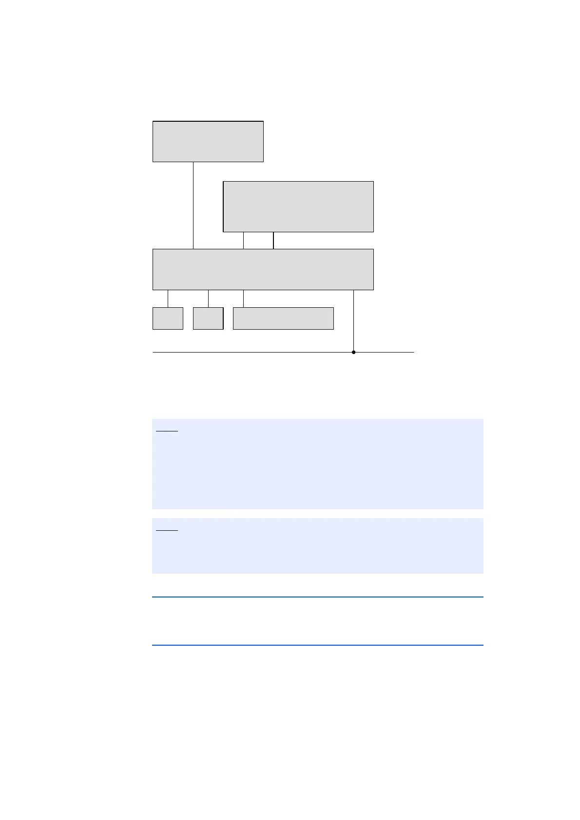
Fig. 4-8 Operation with external switch and iLinkRT
TM
at the ECU interface
To access hardware that is connected to an external switch, the connection
between the Ethernet interfaces "PC" and "ECU" via the internal (software)
switch of ES910.3-A must be disconnected (Ethernet layer 2 software bridge).
4.12.2 Hardware Detection and Protocols
The ES910.3-A detects the directly or via external switch connected hardware
(XETK/ECU or iLinkRT
TM
bus) and automatically uses the required protocol.
4.12.3 "XETK / ECU with Ethernet Interface" Operating Mode
The ECU interface of the ES910.3-A uses an Ethernet connection in duplex oper-
ation for data transfer. The universal ASAM measure and calibration protocol
XCP is used for serial communication. The link to the ECU or the XETK corre-
sponds to the XCP specification V1.0.0.
If an external switch is connected to the ECU interface and the iLinkRT function
is used at the external switch, the internal switch on the web interface of the
module must be configured with the setting "L2 Bridge off" (see chapter 5.6.6
on page 63).
Without this setting, data losses or other errors of ES910.3-A may occur even
after minutes of a functional operation.
In the delivery state, the ECU interface of ES910.3-A is configured for opera-
tion with an external switch ("L2 Bridge off" setting on the web interface of the
module).
ES910.3-A
Sw i t c h
(ES510, ES600, ...)
PC
XETK XETK
PC ECU
Daisy Chain Modules
iLinkRT
TM