3025SW Master Control Switching & Channel Branding
Page 154 Revision 1.0
8.2.1.1. TCP/IP
Alternately, the 3025SW can be configured to receive EAS messages and audio over TCP. The
3025SW firmware implements the DVS/168 protocol, referred to informally as EAS over TCP/IP. FTP
is used to send text files to insert as crawls and WAV files to play as audio clips.
EAS over TCP/IP (EAS over Ethernet) is supported with Trilithic's EASy Plus box and DASDEC. For
further details, refer to the step-by-step instructions in the Trilithic “EASyPlus” Setup Tech Note.
8.3. EAS DECODER INTERFACE (EAS OPTIONED UNITS ONLY)
The 3025SW with the EAS option fitted is the perfect solution for on-air insertion of channel branding
bugs and Emergency Alert System messages. The 3025SW is designed to interface with serial port
based EAS decoders and to Ethernet based EAS decoders. The emergency alerts from these
decoders are inserted over the program video and/or audio.
This section describes how to connect the Sage, TFT or DASDEC serial port based EAS decoders to
the 3025SW, how to configure those decoders and the 3025SW and to perform tests to verify the
system is functioning properly. The Setup of the Trilithic over serial is similar to the Sage serial setup
(however, we do not have a Trilithic Decoder Configuration section at this time).
For instructions on configuring the Trilithic EAS decoder for operation over TCP refer to the Technical
Note titled, “Trilithic EASyPlus Setup”. For using the DASDEC device over TCP, refer to the DASDEC
guide (section 8.3.4).
8.3.1. Connecting the EMC to the EAS Decoder
Make sure that the basic video and audio connections are wired. You will also have to route the output
program video to an appropriate monitor to view the on-screen scrolling messages generated by the
3025SW’s built in character generator. Please ensure that your 3025SW is out of the broadcast path
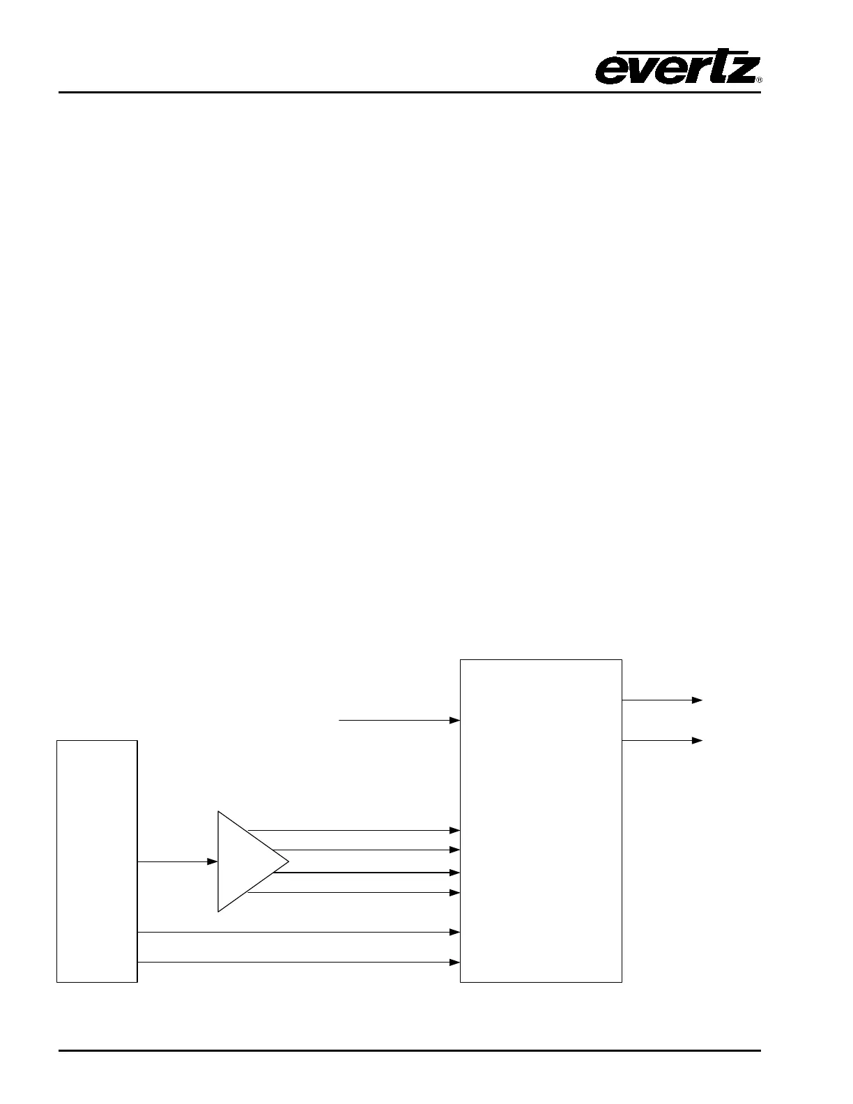
when testing functionality. Figure 8-2 gives a simplified connection overview
EAS
DECODER
3025EMC
7720ADC-A4
MADI IN 1 – VO1 1&2
MADI IN 2 – VO1 3&4
MADI IN 4 – VO2 3&4
MADI IN 3 – VO2 1&2
Tally O/P
Text CG
RS232
GPI – VO Enable
RS232 – Serial 3,4
or 6
Video
Inputs
Preset
Output
Program
Output
Figure 8-2: AS Decoder Connection