3025SW Master Control Switching & Channel Branding
Page 20 Revision 1.0
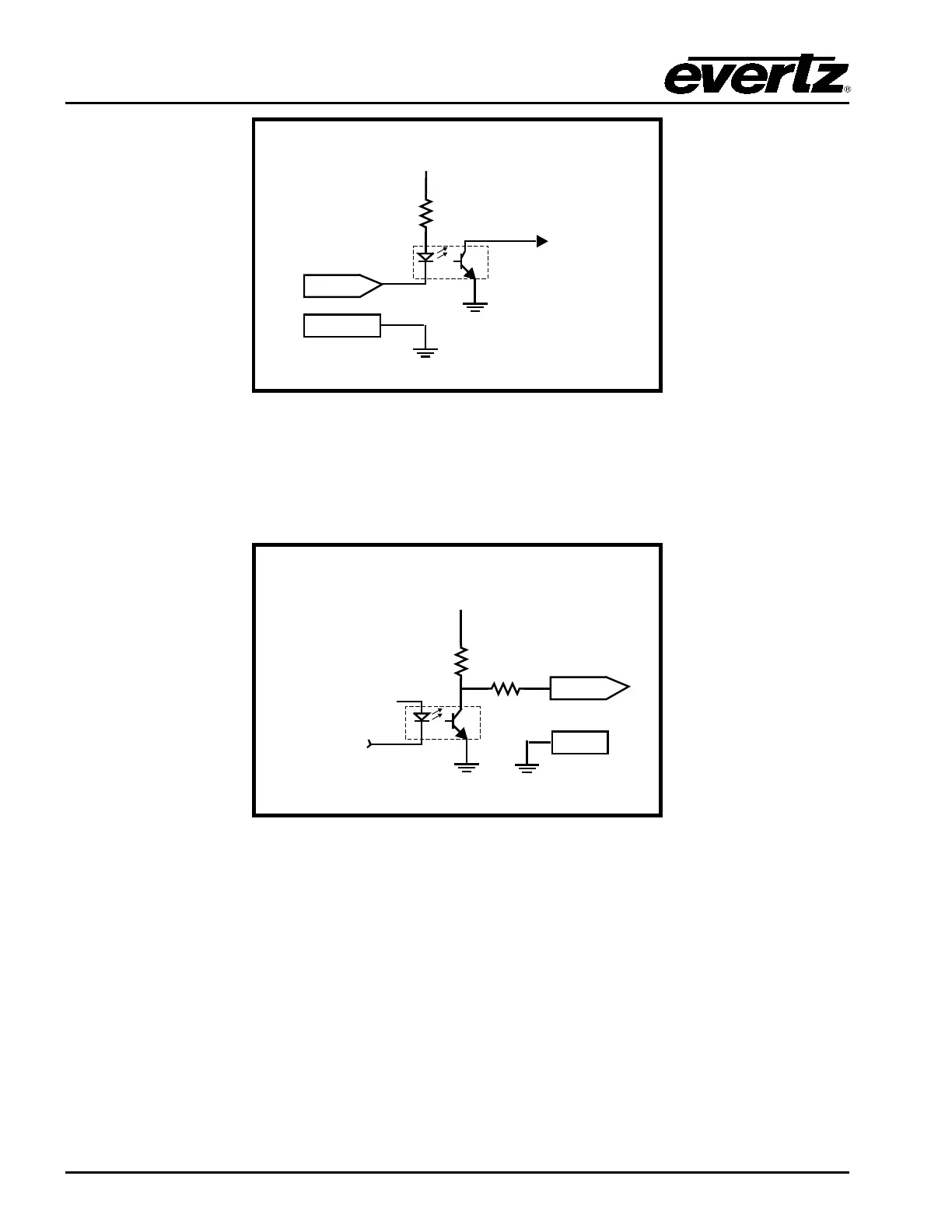
GND
To Internal
Circuit
4.7 k
Ω
GPI
+ 5 Volts
Figure 2-8: GPI Input Circuitry
The GPOs are active low with internal pull-up (10kΩ) resistors to +5 V. When the output goes low, it is
able to sink up to 10 mA; when the output goes high, the signal will go high (+5 V). Do not draw more
than 100
µA from the output. Figure 2-9 shows the circuit for the general-purpose output.
From Internal
Circuit
10k
Ω
+ 5 Volts
GND
GPO
10
Ω
Figure 2-9: GPO Output Circuitry
The GPI and GPO functions are configured using EMC-Setup.