3025SW Master Control Switching & Channel Branding
Revision 1.0 Page 27
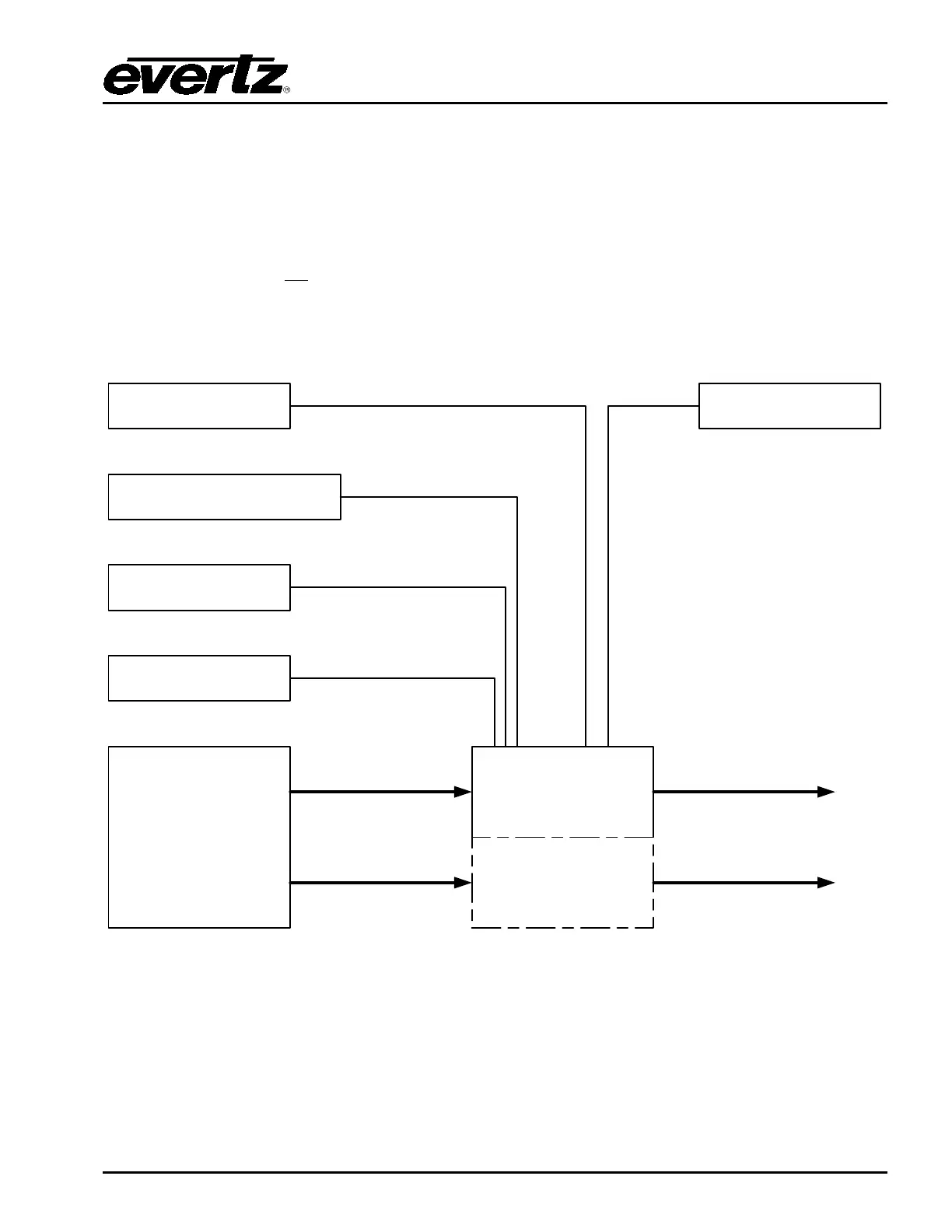
3. 3025SW CONFIGURATION
This section describes the configuration of the 3025SW Switcher. In most applications the 3025SW will
be controlled by an automation system and several industry standard third party systems are supported.
A range of LCD button control panels can be added to the 3025SW, as a backup or simply for manual
control.
An upstream router is not
required to select the input sources available to the 3025SW. The video
sources are connected to the inputs of the 3025SW (up to a maximum of 14 for PGM/PST depending on
the 3025SW channel configuration in EMC-Setup) and the internal router is used when switching sources
and transitioning between PGM/PST.
CONTROL PANEL
EMERGENCY ALERT SYSTEM
NORTH AMERICA ONLY
AUTOMATION SYSTEM
TEMPERATURE PROBE
SDI VIDEO FEEDS
(CORE ROUTER/PLAYOUT)
3025SW
MASTER CONTROL
SWITCHER
3025SW
MASTER CONTROL
SWITCHER
2
ND
CHANNEL
SERIAL/ETHERNET
SERIAL
SERIAL
ETHERNET
CONFIGURATION PC
EMC-SETUP
OVERTURE SUITE
ETHERNET
VIDEO
VIDEO
VIDEO
VIDEO
Figure 3-1: 3025SW System Diagram