3025SW Master Control Switching & Channel Branding
Revision 1.0 Page 25
2.17.1. Power
The power entry module contains a standard IEC 320 power inlet connector, two 5 x 20 mm fuse
holders, and an EMI line filter. The control panel comes with an auto-ranging power supply that
automatically senses the input voltage over the range of 100 to 240 VAC.
Power should be applied by connecting a three-wire, grounding-type power supply cord to the power
entry module on the rear panel of each power supply. For use in North America, the power cord should
be a minimum 18 AWG wire size; type SVT marked VW-1, maximum 2.5 m in length. For use outside
North America, use a power cord approved for the country of use with a minimum 1.00 mm
2
wire size.
CAUTION: To reduce the risk of electric shock, grounding of the gr
of the main plug must be maintained.
For NEBS compliant installations, the AC power cord of the frame shall be
connected to an external surge protection device.
2.17.2. Connecting the Control Panels using Ethernet
The control panels for 3025SW are designed for connection using 10Base-T (10 Mbps), 100Base-TX
(100 Mbps) Ethernet cabling systems. There are two Ethernet ports labelled ETHERNET A and
ETHERNET B, to provide for redundancy in the control system. As a result, either port may be used for
connection to the 3025SW modules without compromise. “Straight-Through” Ethernet cables may be
used when connecting the control panels to an Ethernet hub.
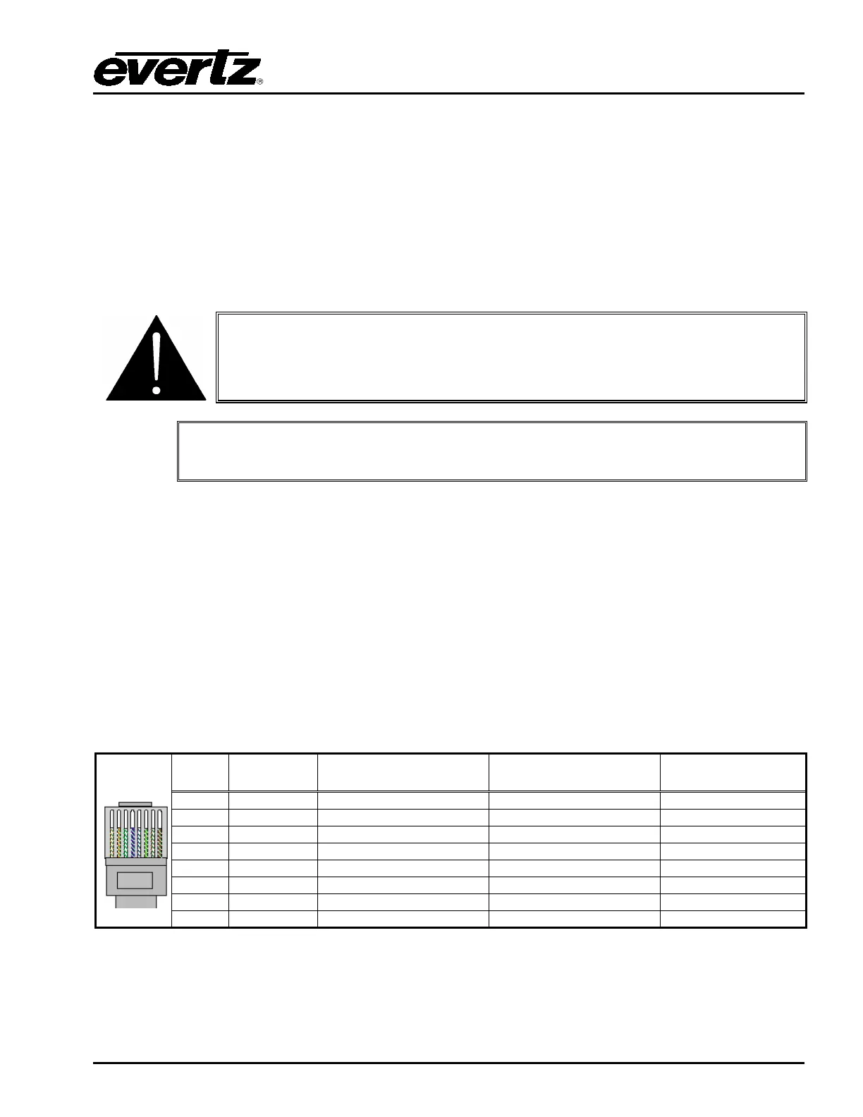
Straight-through RJ-45 cable can be purchased or can be constructed using the pinout information in
Table 2-8: . A colour coded wiring table is provided in Table 2-8 for the current RJ-45 standards
(AT&T 258A or EIA/TIA 258B colour coding shown).
Also refer to the notes following the table for additional wiring guide information.
Pin
1
Pin # Signal EIA/TIA 568A
AT&T 258A or
EIA/TIA 568B
Table 2-8: Standard RJ-45 Wiring Colour Codes