3025SW Master Control Switching & Channel Branding
Page 18 Revision 1.0
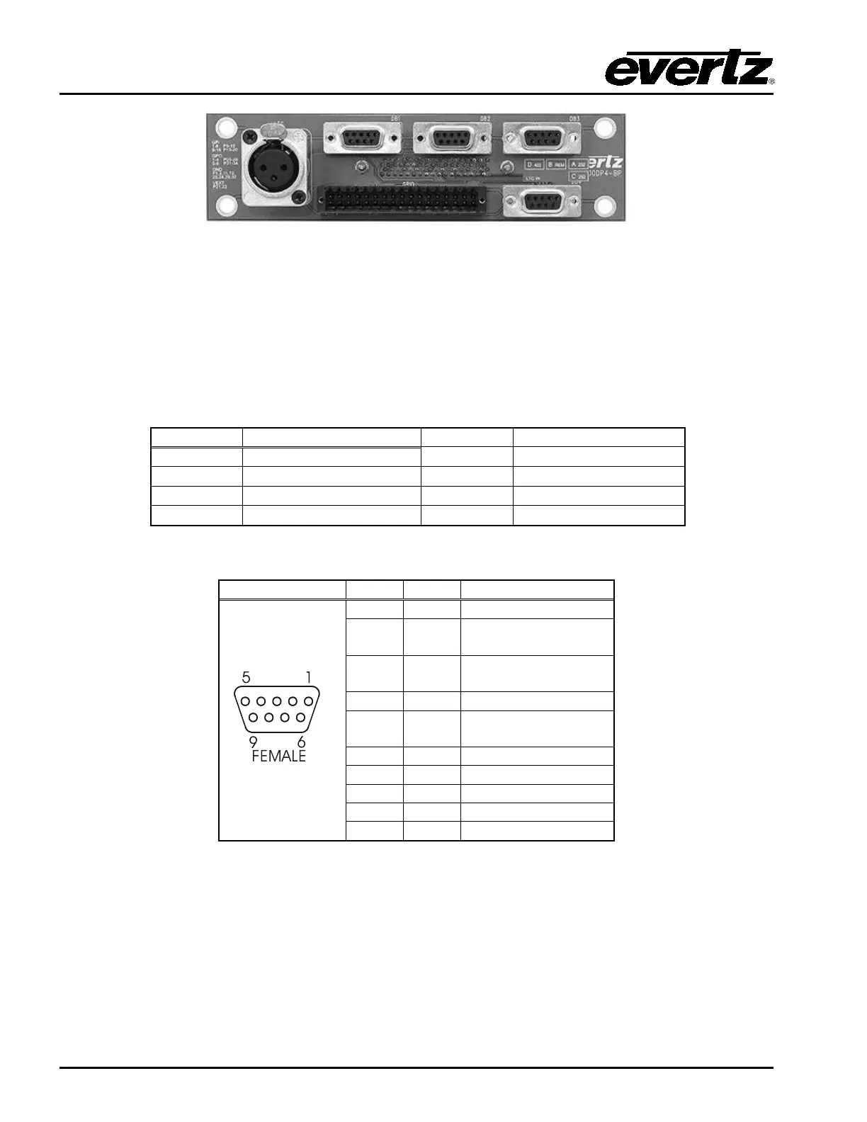
Figure 2-7: Breakout Panel
2.9.4.1. Serial I/O on the Breakout Panel
The AUXIO-1 panel has four serial ports that can be used. The functions can be configured using EMC-
Setup. The ports are divided into two ports that are RS-232 and two that are RS-422. Before the serial
ports can be used they must be configured from the EMC-Setup program to have the controlling protocol
and baud rates set correctly. AUXIO-2 has two additional serial ports that can be used.
Table 2-1: Serial Ports
2
TxD
3
RxD
5
Table 2-2: RS-232 Pin Outs