3025SW Master Control Switching & Channel Branding
Revision 1.0 Page 49
AUDIO
PRE
SHUFFLER
AUDIO
DE-EMBEDDER
SAMPLE RATE
CONVERSION
(SRC)
VIDEO
INPUTS
DISCRETE
AUDIO
INPUTS
PGM
VO2
VO1
EMG
PST
VO4
VO3
AUDIO
GAIN
CONTROL
PGM
VO2
VO1
EMG
PST
VO4
VO3
AUDIO
SHUFFLE
PGM
VO2
VO1
EMG
PST
VO4
VO3
AUDIO
MIXER
PGM
CLN
PVW
AUDIO MONITORING ROUTING
AUX
LOCATION
1
LOCATION
3
LOCATION
2
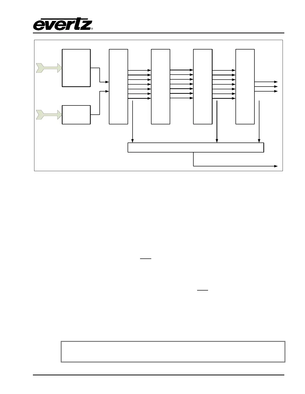
Figure 4-14: Audio Monitoring Location
Location 1 – Output of the Preshuffler
Audio from the output of the pre-shuffler stage in the audio processing pipeline routes audio from
directly after the pre-shuffler. This is input audio before any processing (before shuffling, gain
adjustment and mixing). Program, Preset, Emergency and Voiceovers 1-4 apply as input buses at this
stage.
Location 2 – Mixer Input
Audio from the input to the mixer stage in the audio processing pipeline routes audio from directly
before the audio mixer. This is now audio after
any applied gain adjustment and shuffling. Program,
Preset, Emergency and Voiceovers 1-4 apply as input buses at this stage.
Location 3 – Mixer Output
This is audio from the output of the audio mixer. This is audio after
any applied gain adjustment,
shuffling and mixing. Although CLN output is an option as a route this is not currently supported.
The video routing of the Auxiliary Bus still applies. The audio monitoring routing is selecting the audio
routing for the audio and has no effect on the video.
Further control of the audio monitoring adjustment can be made using any of the supported control
panels. See section 9.1 for more details.
Please note: When Audio Monitoring is enabled V/O5 is no longer available to be
used as a Voiceover.